
Related Manuals for Trotec Q500


Summary of Contents for Trotec Q500
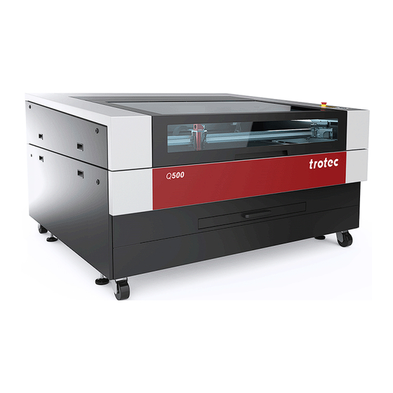
- Page 1 Q500 Operating manual 8057 Operating manual 8057_4.0_EN (05/2023) ENGLISH (Translation)
- Page 2 +31 850 70 51 55 +48 22 339 35 39 +52 55 5351-7252 support@troteclaser.nl serwis_pl@trodat.net mexico@troteclaser.com Trotec Laser (XIAMEN) CO., LTD. #5 GuAn Road South, MaXiang Trotec Laser Inc. Rubber Stamp & Engraving Town +1 866 226 8505, Option 2...
- Page 3 Trotec Laser GmbH Freilingerstraße 99 4614 Marchtrenk, Austria General contact to Technical Support: Tel.: +43 7242 239-7000 E-mail: techsupport@troteclaser.com WWW.TROTECLASER.COM...
- Page 4 Technical Changes Technical specifications are subject to change without notice. Trotec Laser GmbH reserves the right to improve or modify any of the products without prior notice. © Copyright This documentation with all illustrations is intellectual property of Trotec Laser GmbH. The entire documentation is given to the user for personal use only.
-
Page 5: Table Of Contents
Content Content General Information....................... 8 Information about this manual..........................8 Explanation of symbols...............................9 Liability and warranty..............................10 Scope of delivery (standard configuration)......................11 Type plate..................................12 Safety........................... 13 General safety notes..............................13 2.1.1 Intended use................................13 2.1.2 Improper use................................13 2.1.3 Residual risk................................14 2.1.4 Machine modification............................ - Page 6 Content In case of emergency..............................25 Technical Data......................26 Exhaust system requirements..........................27 Materials..................................29 Machine overview......................32 General overview................................32 Laser power potentiometer............................. 33 Tables.................................... 33 Cleaning drawer................................34 Lens(es)..................................34 Nozzles..................................35 Transport........................36 Safety notes................................. 36 Delivery state................................36 Temperature and humidity............................37 Required tools for unloading and transport......................38 Place of storage................................
- Page 7 Mirror..................................61 8.3.5 Motion system................................63 8.3.6 Cleaning drawer..............................64 8.3.7 Lubricating motion system........................... 64 Troubleshooting......................68 Error, cause and remedy............................68 How to create a service file............................69 Contact details......................71 Disassembly........................72 Disposal........................73 Appendix........................74 13.1 CE 8057 Q500................................78 13.2 Datasheet 8057_Q500_Rev3.............................79...
-
Page 8: General Information
General Information General Information For the sake of readability, gender-neutral endings are not used in this operation manual. It is hereby expressly stated that all parts of the text where natural persons or groups of persons are mentioned refer to people of all genders. Information about this manual Before beginning any work on the machine, read this manual completely and carefully. -
Page 9: Explanation Of Symbols
General Information Explanation of symbols Important technical safety notes and instructions in this manual are indicated by symbols. It is important to observe and follow these notes and instructions on workplace safety. Avoid accidents, personal injury and material damage to property by acting with extreme caution. -
Page 10: Liability And Warranty
Furthermore, Trotec Laser GmbH shall accept no liability whatsoever for damage caused by the use of non-original parts and accessories. Additionally, Trotec Laser GmbH shall not be held responsible for any personal injury or property damage, of an indirect or specific nature, consequential loss, loss of commercial profits, interruption to business, or loss of commercial information resulting from use of the equipment described in this manual. -
Page 11: Scope Of Delivery (Standard Configuration)
General Information Scope of delivery (standard configuration) 1. Laser machine 2. Data carrier (with laser soware, printer driver and operating manual) 3. Power cable 4. USB computer connection cable 5. Cleaning kit for optics 6. Lens 7. Focus tool The actual scope of delivery may be different, depending on the special model, additional order options or newest technical changes. -
Page 12: Type Plate
General Information Type plate The type plate with the CE mark is located on the rear of the machine. Enter the serial number, model and year of manufacture into your manual and always refer to them when contacting us for enquiries, troubleshooting or ordering of replacement parts. Serial number: Model: Year of manufacture:... -
Page 13: Safety
Operate the machine only in technically flawless condition and when it fully complies with the EC Machinery Directive. For material details see chapter "List of materials" or contact your local Trotec representative, or our Technical Support. The machine may only be operated with a suitable and effective exhaust system. -
Page 14: Residual Risk
The service operation is therefore declared as laser class 4 (US: class IV) and proper precautions need to be taken (see "Laser classification"). 2.1.6 Applicable safety regulations The following directives and guidelines must be observed to avoid hazards when operating Trotec laser systems:... - Page 15 The operator is responsible for fulfilling all safety requirements, as Trotec Laser GmbH has no influence on the proper use of the machine. Observe the official regulations for your business location in accordance with the applicable local legal regulations (on accident prevention regulations or employee protection), e.g.
-
Page 16: Laser Safety
Safety Laser safety 2.2.1 Laser classification The laser safety class indicates the risk potential from accessible laser radiation. The laser system is a Class 2 (US: Class II) laser marking system as per IEC 60825-1 "Safety of Laser Product". The integrated laser source is a Class 4 (US: Class IV) laser marking system according to IEC 60825-1 and identified as such. -
Page 17: Areas Of Responsibility
Safety Areas of responsibility 2.3.1 Responsibilities of the operator The operator has the following responsibilities: It is the responsibility of the operator to comply with the national official and statutory regulations for the operation • of a class 4 (US: class IV) laser system or laser system with a build in laser source of class 4 (US: class IV). In addition to the safety notes and instructions stated in this manual, consider and observe the local accident •... -
Page 18: Requirements For Operating An Service Personnel
The machine and its components, such as the lens and mirrors, are to be kept clean at all times. • Caution The adjustment of the beam path may only be carried out by service personnel of Trotec Laser GmbH. Requirements for operating an service personnel The requirements for the operating and service personnel are: The personnel must have read and understood this manual and in particular the "Safety"... - Page 19 Safety...
-
Page 20: Safety Devices
Safety Safety devices Technical protective measures 2.7.1 Main switch Pressing the main switch on the backside of the machine to disconnect the machine from the mains power supply. 2.7.2 Key switch Turning the key switch to the "0" position powers off the motor, laser source and electric system. Operation of the machine by unauthorized persons can be prevented by removing the key switch. -
Page 21: Interlock Safety Switches
Safety ACKNOWLEDGE THE EMERGENCY STOP SWITCH 1. Turn the emergency stop switch counterclockwise to unlock it so that the green marking is visible. 2. Restart the laser system using the key switch. 2.7.4 Interlock safety switches Interlock safety switch query the closed status of the acrylic top lid, side panels and front door. If the safety devices are open or not present, the laser cannot be operated. -
Page 22: Secondary (Indirect) Hazards
Safety Secondary (indirect) hazards 2.8.1 Fire hazard Warning Fire hazard Fire hazard from gas and processing of inflammable materials. – Do not operate the device without supervision. – Keep CO fire extinguisher ready at hand in the immediate vicinity of the device. If a main laser beam hits easily flammable material, e.g. -
Page 23: Reflection Through Materials
Safety 2.8.3 Reflection through materials Warning Danger from laser beam. Invisible laser radiation of reflecting materials can cause serious injury or material damage. – Only material according to the intended use of the machine may be used. – Do not use material with high reflecting surfaces such as aluminum, chromium, precious metals, metal foils, stainless steel, brass, copper and titanium. -
Page 24: Hazards Due To Damaged Optics
Safety 2.8.4 Hazards due to damaged optics Warning Damage to optics. Soiled optics absorb laser radiation and can thus be destroyed. Broken or damaged lenses as well as thermal decomposition of lenses release particles which cause serious damage to the health. –... -
Page 25: In Case Of Emergency
• Notice Aer a deletion, Trotec Technical Support must be involved before the system is put back into operation. WHAT TO DO IN THE EVENT OF AN ACCIDENT, FIRST AID If eye damage occurs due to laser radiation, the casualty must present to an ophthalmologist immediately. -
Page 26: Technical Data
Technical Data Technical Data The technical data sheet can be found in the appendix of this manual. -
Page 27: Exhaust System Requirements
Vent Set for R & Q 500: (230V, 50Hz, Euro Plug), (115V, 60Hz, US Plug) • or equivalent • The requirements for the exhaust system and recommended Trotec exhaust systems for standard applications depend on the working table installed in the machine. Notice Connection has to be carried out by our Technical Support. - Page 28 Technical Data Notice The exhaust power available for the application will be reduced by e. g. bends, small hose diameters and long hoses. You should therefore note the following: – Avoid bends. – Keep hose as short as possible. – Use hose diameters as large as possible.
-
Page 29: Materials
Technical Data Materials List of material Material EN Material DE Cutting Engraving Marking Metal Aluminum Aluminium ✓ Aluminum, anodized Aluminium, eloxiert Chromium Chromium Verchromte Oberflächen Precious metal Edelmetalle Metal foils up to 0.5mm Metallfolien bis zu 0,5mm (Aluminum, Brass, Copper, (Aluminium, Messing, precious metal) Kupfer, Edelmetall) - Page 30 Technical Data Plastic ✓ ✓ Acrylonitrile butadiene Acrylnitril-ButadienStyrol- styrene (ABS) Copolymer (ABS) ✓ ✓ Acrylic/PMMA, i.e. Plexiglas® Acryl(PMMA), z.B. Plexiglas® ✓ ✓ Rubber Gummi (Stempelgummi) ✓ ✓ Polyamide (PA) Polyamid (PA) ✓ ✓ Polybutylene terephthalate Polybutylenterephthalat (PBT) (PBT) ✓ ✓ Polycarbonate (PC) Polycarbonat (PC) ✓...
- Page 31 You have additions for further materials for us or in your opinion a material was not listed. We recommend performing a material processing test with the above mentioned material, using the appropriate configuration. Trotec Laser GmbH assumes no responsibility for any consequences of laser processing in any application, especially with medical or pharmaceutical applications.
-
Page 32: Machine Overview
Machine overview Machine overview General overview Description Description Acrylic top lid Emergency stop button Table Keypad Side panel Rolls Side panel for power supplies Levelling feet Cleaning drawer Cover for cleaning opening Cover for laser source Cover/connection for exhaust tube... -
Page 33: Laser Power Potentiometer
Machine overview Laser power potentiometer Using the Laserpower potentiometer (available as an option), you can electrically adjust the laser power during the engraving or cutting process. cutting process. Adjustments of ± 20% are possible. This application can be used, for example, to increase the laser power when cutting outer contours, so that the job does not have to be started again. -
Page 34: Cleaning Drawer
Machine overview ALUMINUM CUTTING GRID TABLE This robust cutting table offers excellent stability and is particularly suitable for cutting tasks with work pieces smaller than 100 mm, as these remain in a flat position aer cutting. Cleaning drawer The cleaning drawer serves as a dust collection container and can be pulled out and cleaned aer processing. -
Page 35: Nozzles
Machine overview Nozzles 3mm diameter 7mm diameter (0.12 inches) (0.28 inches) -
Page 36: Transport
Transport Transport Safety notes Warning Risk of injury There is risk of injury from falling parts during transport, loading and unloading of the machine. – Follow the safety notes. Observe the safety notes to avoid damage to the machine from improper handling during transport: Always move the machine with utmost care and attention. -
Page 37: Temperature And Humidity
Transport OBSERVE THE PACKAGING SYMBOLS: NOTE THE SHOCKWATCH SIGN: Temperature and humidity Transport conditions Transport temperature (ambiente temperature): -10 °C to +40 °C (14 °F to 104 °F) Relative humidity: Maximum 70%, non-condensing Avoid high temperature fluctuations. • Storage conditions Storage temperature (ambiente temperature): 0 °C to +30 °C (32 °F to 86 °F) Relative humidity:... -
Page 38: Required Tools For Unloading And Transport
Transport Required tools for unloading and transport REQUIRED TOOLS: Unloading - Forkli • Transport - Pallet truck • Place of storage Keep the machine sealed in its packaging until it is assembled or installed. • The storage location must be dry, free of dust, caustic materials, vapors and combustible materials. •... - Page 39 Transport 1. Use a forkli truck to place the transport case on ground level. 2. First remove the top wooden cover and then the side plates of the transport box. 3. Remove the aluminium bag (for sea freight packaging). 4. Position the forks under the machine. Make sure that the machine rests completely.
-
Page 40: Transport Protection For The Axes
Transport 6. Remove the packing material. 7. The machine must be adjusted and installed by a technician (see installation guide Q500). 5.7.1 Transport protection for the axes Information The illustrations used do not correspond to the original condition of the machine and are for information purposes only. - Page 41 Transport 2. Disconnect the power cable. 3. Remove the exhaust system. 4. Reposition the machine (e.g. with auxiliary equipment if necessary) and place it on a level, clean floor. 5. Adjust the machine. 6. Initial commissioning of the electrical system. 7.
-
Page 42: Setup And Installation
Setup and installation Setup and installation For your safety Notice The setup has to be carried out by Technical Support. Temperature and humidity Ambiente conditions Operating temperature (ambiente temperature): +15 °C to +25 °C (59 °F to 77 °F) Relative humidity: 45% to 65%, non-condensing If the system has been exposed to large temperature fluctuations, it must first be brought back to room temperature •... -
Page 43: Space Requirements
Setup and installation Space requirements Observe shielding or sufficient distance to the wall and adjacent objects. Connections → No Description No Description Fuse Connection for cooling water glass laser source... -
Page 44: Mains Connection
Setup and installation No Description No Description Main connection with main switch Connection for cooling water Iradion laser source USB connection for PC Connection exhaust system Chiller alarm Connection table exhaust system Connection for air assist Caution Install the connections exactly in the order described, otherwise electrostatic charging can damage your computer and/or the electronics of the laser system. -
Page 45: Connect The Water Cooling System
Setup and installation 6.4.4 Connect the water cooling system Components: Two cooling circuits A and B on the water cooling system • Two cooling circuits INLET1 and INLET2 on the laser machine • Four water hoses • INLET1 used for single source machines. INLET1 and INLET2 used for dual source machines. - Page 46 Setup and installation The water level must be within the green range. 5. Switch on the system and check the level indicator again. (When all hoses are completely filled, the water level may drop slightly.) 6. Check all hoses for leaks. 7.
-
Page 47: Operation
Operation Operation Before commissioning CHECK THE FOLLOWING POINTS BEFORE COMMISSIONING: Completeness and technically flawless condition of the machine and safety devices. • Order and cleanliness at the workplace. • Cleanliness of optical components (free of dust and dirt). • Activated exhaust system. •... -
Page 48: Installation And Replacement Of The Laser Source
Operation 3. Level the x-axis using a spirit level. Set the machine to the correct height using the height-adjustable feet on the machine. 7.1.1 Installation and replacement of the laser source Caution The laser source must be installed and replaced by a technician. Warning Dangerous electrical voltage High voltage can cause serious injury or even death. - Page 49 Operation 2. Switch on the main power supply using the main switch on the rear of the machine. 3. Turn the key switch to the right and hold it against the spring force. 4. As soon as the machine starts, release the key switch. 5.
-
Page 50: Control Panel
Operation Control panel ❶ Standby-button. LED On: Standby-Mode ❷ Status indicator laser beam. LED On: The machine is processing data. ❸ Stop-button ❹ Start/Pause/Repeat-button LED is flashing slowly green (every two seconds). All covers are closed. Machine is ready. LED is flashing fast green (twice per second). Minimum one cover is open. - Page 51 Operation 7.4.1.1 Description Image Button Description Status indicator LED On: The machine is processing or receiving data. Standby-button LED On: Standby-mode Press this button to switch to the Standby-mode. • Press the Standby-button while the working table is moving • up or down (e.g.
- Page 52 Operation Image Button Description Start/Pause/Repeat-button Start: Press this button to start a job. The job has to be on the • plate in JobControl®. Pause: Press this button to pause the job (LED On) which is • currently being processed. Press this button again to continue the job (LED Off).
-
Page 53: Changing The Lens
Operation Changing the lens 1. Remove the air assist 2. Open the thread on the hose. upper side. 3. Open the thread on the 4. Remove the tube from bottom. the laser head. 5. Unscrew the lens holder 6. Here: Take the 2.0 inch from the tube. -
Page 54: Position Of The Lens
Operation 9. Tighten the thread again. 10. Reconnect the air assist hose. Position of the lens Assembly without lens Assembly with a 2.0 inch lens Assembly with a 4.0 inch lens Notice Make sure that the lens is placed with the convex side facing upwards. -
Page 55: Focusing
Operation Table placement 1. Remove the table including frame from the machine. 2. Insert the new table including frame into the machine. Information The slats and the frame are transported individually. The slats can be positioned individually in the frame as required. - Page 56 Operation 1. Use the X/Y position keys (1) on the control panel to move the processing head over the material to be engraved. 2. Place the focus tool (2) on the processing head. 3. Turn down the processing head with the adjusting screw (3) until the focus tool falls down.
-
Page 57: Options
Operation Options 7.9.1 JobControl Vision With the JobControl® Vision additional option, a camera is located at the laser working head which reads the register marks on the plate material. This allows distortions in the print to be detected and compensated for. The material is cut to fit exactly. Production times are accelerated and cost-intensive incorrect cuts are avoided. -
Page 58: Maintenance
Maintenance Maintenance Safety notes Danger Improper maintenance can cause serious injury or damage. Maintenance may be carried out only by authorized, trained personnel who are familiar with how to operate the machine and in strict observance of all safety notes. Danger Risk of fire or explosion. -
Page 59: Cleaning
Maintenance System Components Daily Weekly Quarterly Half-yearly Yearly Vent slots of exhaust box. ✓✓ (inside the machine) Entire working area. ✓ General cleaning. Vent slots (backside of the ✓✓ maschine) Spindles Clean and grease. Cover of the laser source and ✓... -
Page 60: Optics In General
Maintenance 8.3.2 Optics in general Trotec Laser GmbH recommends to use the cleaning set enclosed. Alternatively, use high-quality cotton swabs together with the provided cleaning liquid. Notice The following cleaning products are available as accessory parts: – Lens cleaning cloth –... -
Page 61: Mirror
Maintenance 7. Retighten the thread. 8. Reconnect the air assist hose. 8.3.4 Mirror CLEANING MIRROR #3 ON THE WORKING HEAD 1. Unscrew the two screws 2. Loosen the mirror by by hand. wiggling it slightly. 3. Remove mirror. 4. Clean the mirror carefully. 5. - Page 62 Maintenance CLEANING MIRROR # ON THE AXIS Quick cleaning with low dirt Remove loose particles and dust with a bellows or compressed air (according to ISO 8573:2010 Class 1) Thorough cleaning for heavy dirt 1. Remove the screws from the mirror. 2.
-
Page 63: Motion System
X-AXIS RAIL CLEANING 1. Clean the entire length of the x-axis rail with a cleaning cloth and a cotton swab. Use a mild cleanser (Trotec) to clean the bearing - contact your local Trotec Service. Notice Aer cleaning is the ideal time to lubricate the axles. -
Page 64: Cleaning Drawer
Maintenance 8.3.6 Cleaning drawer Open the cleaning drawer and remove deposits. 8.3.7 Lubricating motion system LUBRICATION OF THE AXIS RAILS IN X AND Y-DIRECTION Lubrication interval: 150 operating hours or 4 weeks Lubrication quantity: 0.2 cm (2 strokes with grease gun) RECOMMENDED LUBRICANTS Producer Type... - Page 65 Maintenance POSITION 1 OF 3: LUBRICATE Y-AXIS AT FRONT POSITION Remove the right side cover. • Move the x-axis to the far le (front of the working • table). Lubrication nipple should be accessible and concentric • with hole. Press two pump strokes of the grease gun into the •...
- Page 66 Maintenance POSITION 2 OF 3: LUBRICATE X-AXIS Carefully remove the cover plate with an Allen key (SW • 2 mm). Slide the working head to the le until the lubrication • nipple and hole are concentric. Press two pump strokes of the grease gun into the •...
- Page 67 Maintenance POSITION 3 OF 3: LUBRICATE Y-AXIS AT REAR POSITION Remove the le side cover. • Move the x-axis to the far le (back of the working • table). Lubrication nipple should be accessible and concentric • with hole. Press two pump strokes of the grease gun into the •...
-
Page 68: Troubleshooting
Troubleshooting Troubleshooting This chapter should enable the maintenance personnel to identify and resolve operational faults based on error messages and symptoms. Warning Risk of fire from incorrect parameter settings. Laser operation with incorrect parameter settings such as power settings, speed or frequency can result in flame formation. -
Page 69: How To Create A Service File
Troubleshooting Problem Possible cause Remedy The size to be engraved or cut does Raster correction ON in Switch off raster correction in • • not match the size in CorelDraw. JobControl®. JobControl® (settings/advanced options/laser tab). Wrong size settings in the printer •... - Page 70 Troubleshooting 5. The window "Save Service File to” shows up. Select a directory to save the file into and click on "Save”. 6. The window "Add Layout File” appears. Select the layout file that was sent to JobControl® and possibly caused a failure (e.g.: a CorelDraw file, Photoshop file, AutoCAD file,…).
-
Page 71: Contact Details
Contact details Contact details TECHNICAL SUPPORT In case of questions, contact our experienced Technical Support in your local area. For global service contact numbers and further information please see our website, section "Support": www.troteclaser.com When calling, please make sure that the machine is in your immediate vicinity, and that you have the following information ready (see response form): At which working process did the problem occur? What you have done so far to correct the problem. -
Page 72: Disassembly
Disassembly Disassembly Warning Danger of injury when disassembling the machine. There is danger of injury when disassembling the machine. Always wear suitable protective clothing (e.g. safety goggles, safety shoes, safety gloves). Warning Dangerous electrical voltage Electric current. The machine must be disconnected from the main power supply. Notice –... -
Page 73: Disposal
Disposal Disposal Disposal Do not dispose of the machine with domestic waste! Electronic devices have to be disposed of according to the regional directives on electronic and electric waste disposal. In case of further questions, please ask your supplier. In case of disassembly, use suitable tools to dismantle the unit into individual parts. Sort the individual parts and have them disposed of professionally. -
Page 74: Appendix
Appendix Appendix... - Page 75 Acceptance report Dear customer! We request your confirmation of properly completed transfer of the machine. Please transmit a copy of this document - filled out and signed by an authorized company representative - to an employee of our sales affiliate for forwarding to the manufacturer. Please check applicable items: Machine parts checked for shipping damage.
- Page 76 Response form Dear customer! In case of any trouble with the machine, please provide the following information and additional- ly create a service file. Contact details Machine data Name: Serial number: Country: JobControl version: ® Phone: Driver version: E-mail: Layout Software: Date: Firmware version: Description of the problem...
- Page 77 Training verification form Trainee: Trainer: Date of Training: The employee named above was instructed in the operation of the ........laser system. Especially the following topics were covered: Machine function Danger areas Warnings Position of the Emergency stop button Personal protective equipment Operating equipment Workflow Setting-up...
-
Page 79: Datasheet 8057_Q500_Rev3
Technical Datasheet 8057 Q500 DC/RF/DU – Technical Specifications Mechanics Working area 1300 mm x 900 mm (51.18 x 35.43 inches) Loading area 1400 mm x 1150 mm (55.12 x 45.28 inches) Aluminium cutting grid table or aluminium slat cutting table... - Page 80 Technical Datasheet Options and optional accessories Working table Aluminium slat cutting table Lenses 4.0” lens Exhaust / Vent-Set 2x external ventilators incl. accessories (hoses, hose clamps) JobControl® Vision Registration mark recognition and compensation system External variable power meter Adjust the laser power in a range of ± 20% on the fly Control system Laser power Adjustable from 0-100%...
- Page 81 Electrical Power consumption laser 100 – 250V, ~ 1100 - 1500 W Power consumption chiller ~ 900 W or ~ 1800 W for DU-Version Subject to changes without notice. Errors and omissions excepted. Modell Identification: 8057 Q500 DC/RF/DU January 2023...
Need help?
Do you have a question about the Q500 and is the answer not in the manual?
Questions and answers