Table of Contents
Advertisement
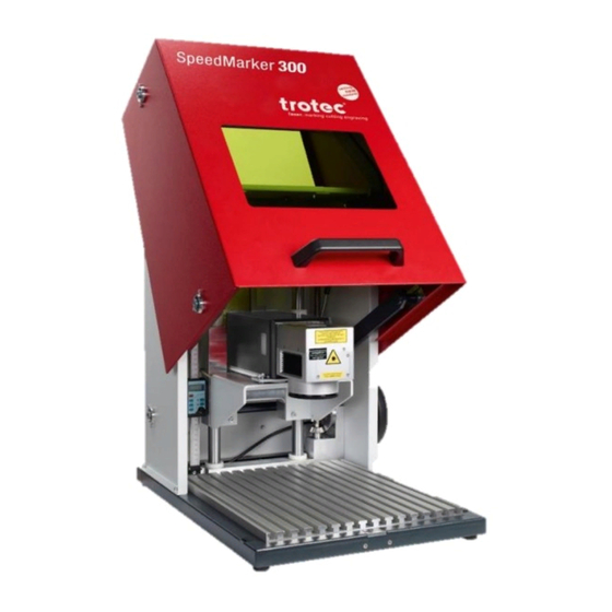
OPERATION MANUAL
SpeedMarker 300 / ProMarker 300
This documentation with all illustrations is intellectual property of Trotec Produktions- u. Vertriebs GmbH.
The entire documentation is given to the user for personal use only. This documentation must not be reproduced or made avail-
able to others without our written permission. Any breach of law will be prosecuted.
Advertisement
Table of Contents


Need help?
Do you have a question about the SpeedMarker 300 and is the answer not in the manual?
Questions and answers