
Related Manuals for Hamamatsu ENERGETIQ LDLS EQ-99X


Summary of Contents for Hamamatsu ENERGETIQ LDLS EQ-99X
- Page 1 Model EQ-99X LDLS ® Laser-Driven Light Source Operation and Maintenance Manual Revision 6 June 2023 DOC-6521...
- Page 2 Copyright Information Copyright © 2023 Energetiq Technology Inc. All rights reserved. For a list of patents that cover Energetiq products, visit www.energetiq.com/patents. All technical information, including drawings, schematics, and specifications contained in this manual are the property of Energetiq and shall not be reproduced in whole or in part without the written consent of Energetiq. The content of this manual is subject to change without notice.
-
Page 3: Table Of Contents
Table of Contents Contents Contents.................................. 3 Chapter 1. Safety and Warranty Information ......................5 1.1 Safety Warnings............................5 1.2 General Precautions ............................. 5 1.3 Laser Information ............................6 1.4 Labels and Safety Notifications ........................7 1.5 Safety Interlocks ............................9 1.5.1 External Interlock............................ - Page 4 Table of Contents Chapter 5. Operating the System ........................... 33 5.1 Starting the System............................. 33 5.2 Stopping the System ........................... 35 Chapter 6. Maintenance ............................36 6.1 Fiber Cleaning Process ..........................36 6.1.1 Fiber Inspection Tools..........................37 6.1.2 Fiber Cleaning Tools.............................
-
Page 5: Chapter 1. Safety And Warranty Information
Chapter 1. Safety and Warranty Information Chapter 1. Safety and Warranty Information 1.1 Safety Warnings WARNING This unit emits ultraviolet (UV) radiation that is harmful to humans. Avoid exposure to the direct or reflected output beam. Make certain that the appropriate output beam shields and optics are in place prior to energizing the unit. -
Page 6: Laser Information
Chapter 1. Safety and Warranty Information Other than the lamp bulb and output window, there are no user-serviceable parts inside the EQ-99X system. For any problems encountered during operation, please contact Energetiq for assistance. If there is a component failure, do not attempt to open the power supply controller or lamp head enclosure of the EQ-99X system. -
Page 7: Labels And Safety Notifications
Chapter 1. Safety and Warranty Information 1.4 Labels and Safety Notifications The following safety labels appear on the product. The figures EQ-99X Power Supply Controller Label Locations and EQ-99X Lamp Head Label Locations show the location of each label on the EQ-99X system. UV Hazard Warning Label – indicates hazardous levels of UV light are present. Heat Warning Label – indicates hazardous levels of heat are present. Laser Label – indicates that a laser light is present. Manufacturer’s Identification Label (Power Supply Controller) – gives the manufacturer’s name and address, and the model, serial number, and date of manufacture of the power supply controller. - Page 8 Chapter 1. Safety and Warranty Information Figure 1. EQ-99X Power Supply Controller Label Locations EQ-99X Operation & Maintenance Manual 8 of 45 ...
-
Page 9: Safety Interlocks
Chapter 1. Safety and Warranty Information Figure 2. EQ-99X Lamp Head Label Locations 1.5 Safety Interlocks The EQ-99X system is equipped with interlocks to prevent operation of the device when any of the following conditions are present: 1. Lamp bulb is not properly installed in the lamp head. 2. The laser fiber is not properly connected to the lamp head. 3. -
Page 10: Chapter 2. System Description
Chapter 2. System Description Chapter 2. System Description 2.1 System Overview The EQ-99X system is a broadband lamp system for use in a wide variety of applications. The lamp bulb produces high brightness, broadband light from DUV wavelengths through visible and beyond. The output is very stable, and the system has a long lifetime before any service is required. A simple control interface ensures ease of use. ... -
Page 11: Power Supply Controller
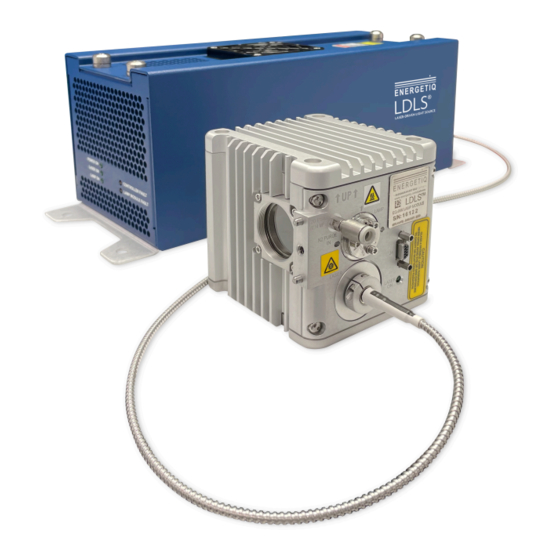
Chapter 2. System Description Figure 3. EQ-99X System The following subsections provide descriptions of the system components and controls and give an overview of their functions. 2.2.1 Power Supply Controller The power supply controller contains the following components: • Status Indicator LEDs •... - Page 12 Chapter 2. System Description Figure 4. EQ-99X Power Supply Controller Components A. Status Indicator LEDs These five LEDs indicate the system status. The function of these indicators is shown below in the table Status Indicator LED Functions. ...
- Page 13 Chapter 2. System Description LED Label Meaning (when lit) One of the following has occurred in the lamp head: 1. Control cable not connected properly 2. Lamp head internal temperature too high LAMP MODULE FAULT 3. Laser fiber not correctly connected 4.
-
Page 14: Lamp Head
Chapter 2. System Description 2.2.2 Lamp Head The lamp head contains the following components: • Lamp Output Window • Laser ON Indicator • Nitrogen Purge Inlet • Laser Input • J4 Signal Port • Lamp Bulb (internal, not shown) • Igniter (internal, not shown) •... - Page 15 Chapter 2. System Description C. Nitrogen Purge Inlet This is the inlet fitting for nitrogen purge gas. Purge gas is optional but strongly recommended for best performance. For optimal product performance, nitrogen gas purging of the EQ-99X system is required. If nitrogen purge gas is not used, shorter lifetime and faster output degradation (especially in the ultraviolet wavelength range) is expected.
-
Page 16: Chapter 3. System Specifications And Requirements
Chapter 3. System Specifications and Requirements Chapter 3. System Specifications and Requirements 3.1 Optical Performance See the figure Typical Output Spectrum below for the typical output spectrum. Figure 6. Typical Output Spectrum 3.2 Physical Specifications Dimensions (H x W x D) • Lamp Head: 82 x 86 x 76 mm (3.2 x 3.4 x 3.0 in) •... -
Page 17: Utility Requirements
Chapter 3. System Specifications and Requirements Digital Outputs • Type: Open collector to ground (digital common) • Logic: Active Low • Voltage: 30VDC max. • Sink Current: 30mA max. User Power • Voltage: 5VDC, referenced to digital common •... -
Page 18: Chapter 4. Installation
Chapter 4. Installation Chapter 4. Installation 4.1 Unpacking the System Upon arrival, inspect all parts of the EQ-99X system for completeness and damage incurred in shipping. Use care when unpacking to avoid damaging the laser fiber optic cable. If any part is missing or appears damaged, contact Energetiq immediately. Do not attempt to substitute any parts. ... -
Page 19: Optional Accessories
Chapter 4. Installation Qty Item Description Picture Black interconnecting cable from lamp head to power supply controller (9 pin mini D-sub) 4.1.2 Optional Accessories The EQ-99X system shipping box may also contain the following optional accessories available from Energetiq: Table 4. Optional Accessories in Shipping Box Item Description Picture EQ-99-RC Remote Control with interlock jumper plug and 15-pin D-connector I/O cable 12 VDC Power Supply (universal input voltage) ... -
Page 20: Tools Required
Chapter 4. Installation 4.2.1 Tools Required Table 5. Required Tools Description Quantity Nitrile Safety Gloves 1 pair Complete EQ-99X system (Power Supply Controller and Lamp Head) 1 Fiber Inspection Microscope 4.2.2 Procedure To attach the laser fiber optic cable from the power supply controller to the lamp head: Note: The lamp head pictured in this procedure may appear slightly different than the lamp head included with your EQ-99X system. - Page 21 Chapter 4. Installation Figure 8. Removing the Protective Cap 3. Using the fiber inspection microscope, inspect the laser fiber optic cable for contamination as outlined in the section 6.1 Fiber Cleaning Process. If contaminated, clean the fiber optic cable as described. 4.
- Page 22 Chapter 4. Installation Figure 10. Inserting the Laser Fiber Optic Cable Caution: Ensure the output fiber tip does not contact any surface (table, lamp head exterior, etc.) to avoid scratching or damaging the cable. 6. Screw in the laser fiber connector to tighten the connector to the lamp head. Rotate the laser output fiber to ensure the thick black line on the fiber optic cable is on top at the 0-degree position.
-
Page 23: Installation Procedure
Chapter 4. Installation 4.3 Installation Procedure The following section details how to install the EQ-99X system. Note: The EQ-99X system is typically delivered with the laser fiber optic cable connected to the lamp head. This is done to minimize the possibility of debris or particles contaminating the end of the laser fiber. Energetiq strongly recommends leaving the laser fiber optic cable connected unless it is necessary to disconnect it for installation or routing of the laser fiber. - Page 24 Chapter 4. Installation 2. Mount the power supply controller to an optical breadboard plate or other suitable mounting structure using the four supplied holes in the tabs on the bottom of the chassis. Ensure the inlet and outlet air vents of the power supply controller are not blocked.
- Page 25 Chapter 4. Installation Figure 14. Mounting the Lamp Head 5. Set up the lamp head with appropriate ultraviolet safety measures in place. It is recommended that any enclosure or aperture-blocking hardware utilizes switches wired to the EQ-99X system external interlock circuit. 6. Connect the black 9-pin mini D-sub interconnect cable from the power supply controller (labeled TO LAMP) to the lamp head (labeled J4).
- Page 26 Chapter 4. Installation Figure 16. Connecting the I/O Cable to Remote Control On the back of the remote control, insert the interlock jumper plug into the interlock port. Figure 17. Inserting the Interlock Jumper Plug Alternatively, if you are integrating the EQ-99X system into your own interlock system, connect a remote contact or solid-state switch across pins 1 and 3 in the interlock port. EQ-99X Operation & Maintenance Manual 26 of 45 ...
- Page 27 Chapter 4. Installation Figure 18. Interlock Pin Locations If using another remote control system, see 4.4.2 Installing Alternative Remote Control for more information. 9. Connect the 12VDC input power source to the power supply controller and a power outlet. Figure 19. Connecting the 12VDC Input Power Source Alternatively, if using another power supply, see 4.4.1 Installing Alternative Power Supply for more information. The system is now ready to operate. EQ-99X Operation & Maintenance Manual 27 of 45 ...
-
Page 28: Installing Alternative Power Supply Or Remote Control
Chapter 4. Installation 4.4 Installing Alternative Power Supply or Remote Control If you are using a power supply other than the included 12VDC Power Supply, or if you are using a or a remote control other than the EQ-99RC Remote Control, the following subsections detail how to install an alternative power supply or remote control for the EQ-99X system. ... - Page 29 Chapter 4. Installation LASER ON Pulled to digital common when ON LAMP MODULE Pulled to digital common when OK, float on FAULT FAULT CONTROLLER Pulled to digital common when OK, float on FAULT FAULT ISOLATED +5V 50mA maximum, referenced to digital common SUPPLY DIGITAL COMMON ...
- Page 30 Chapter 4. Installation Figure 20. Remote Interface Schematic EQ-99X Operation & Maintenance Manual 30 of 45 ...
-
Page 31: Water Cooling Components For Eq-99 Cal
Chapter 4. Installation 4.6 Water Cooling Components for EQ-99 CAL Note: The following procedure only applies to the EQ-99-CAL model of the EQ-99X system. The following section details how to connect the water cooling components that come packaged with the EQ-99-CAL system. - Page 32 Chapter 4. Installation The ¼” end of the Swagelok fitting will connect to the two pieces of ¼” OD tubing as shown in the figure EQ-99- CAL Lamp Head Assembly. a. A 9/16” and ½” wrench are required in order to complete the connection. 3. Connect the open ends of the ¼” tubing to the “inlet” and “outlet” ports on the Solid State Cooling Systems UC160-190 Chiller. a. The ports on the chiller are “quick disconnect” fittings. To create a good seal, press the tubing in. b. There are no designated ports for the two pieces of tubing. Either piece of tubing can fit in either port. Figure 22. Assembled EQ-99-CAL Lamp Head ...
-
Page 33: Chapter 5. Operating The System
Chapter 5. Operating the System Chapter 5. Operating the System 5.1 Starting the System Caution: Once the EQ-99X system is properly set up, verify that all personnel that will be in contact with the system are aware of the potential hazards involved as described in Chapter 1. Safety and Warranty Information. It is the responsibility of the user to verify that the EQ-99X system is safely being used. - Page 34 Chapter 5. Operating the System Figure 24. LASER ON LED Illuminated 3. In approximately 20-150 seconds, the igniter automatically turns on and the plasma ignites. The LAMP ON LED light illuminates. Figure 25. LAMP ON LED Illuminated 4.
-
Page 35: Stopping The System
Chapter 5. Operating the System unit has reached the optimum conditions for ignition. – If a bulb fails to ignite, 150 seconds after the OPERATE switch is turned ON: • the LASER ON LED will be OFF. • the LAMP FAULT LED will be ON. • the LAMP ON LED will remain OFF. This is very unusual. However, if this occurs, turn the OPERATE switch to the OFF position ("down" position) and restart this procedure at Step 1. If this issue occurs multiple times, see Chapter 7. -
Page 36: Chapter 6. Maintenance
Chapter 6. Maintenance Chapter 6. Maintenance 6.1 Fiber Cleaning Process Fiber Cleaning Basics • Operating the LDLS with a contaminated fiber introduces the risk of decreased performance or damage to the unit. • A fiber is considered clean when there are no particles on the fiber core or cladding that are detectable with >200X magnification. ... -
Page 37: Fiber Inspection Tools
Chapter 6. Maintenance 6.1.1 Fiber Inspection Tools Figure 26. JDS Uniphase/Westover FVD-2400 Benchtop Figure 27. FS-201 Handheld Fiber Inspection Scope USB/PC Operated Fiber Viewer Note: A special SMA adapter must be used with either the FS201 handheld inspection scope or the Westover Digital inspection scopes. This custom adapter allows the scope to be used with the laser fiber and integral interlock ring. The custom adapter may not be compatible with other fiber inspection equipment. ... -
Page 38: Fiber Inspection And Cleaning Procedure
Chapter 6. Maintenance Table 9. Chemtronics QbE Cleaning Platform Part Description Manufacturer Part Number UPC Chemtronics QbE Cleaning Platform QbE 32599094887 6.1.3 Fiber Inspection and Cleaning Procedure Caution: Disconnect power from the power supply controller before performing fiber inspection. Figure 28. Fiber Cleaning Process Flowchart •... -
Page 39: Lamp Bulb Replacement
Chapter 6. Maintenance Figure 29. Contaminated and Clean Fiber End Examples 6.2 Lamp Bulb Replacement If a bad lamp bulb is suspected in the EQ-99X system, contact Energetiq for more information on having the lamp bulb replaced. ... -
Page 40: Chapter 7. Troubleshooting
Chapter 7. Troubleshooting Chapter 7. Troubleshooting As shown in the figure Power Supply Controller LED Lights below, there are five LED lights on the side of the power supply controller that indicate the current status of the EQ-99X system. Figure 30. Power Supply Controller LED Lights During normal operation, the three green LED lights on the left-hand side (POWER ON, LASER ON, LAMP ON) should be turned ON. -
Page 41: Issues And Remedies
Chapter 7. Troubleshooting 7.1 Issues and Remedies See below for a list of possible issues that may be encountered while operating the EQ-99X system and the potential steps to resolve those issues. Table 10. Possible Issues and Remedies LED Light Name Possible Issues Troubleshooting Steps and Status One of the following has occurred in the lamp head:... - Page 42 Chapter 7. Troubleshooting LED Light Name and Possible Issues Troubleshooting Steps Status The plasma inside the lamp bulb has been LAMP ON extinguished after ignition. This also causes the is OFF LAMP MODULE FAULT light to turn ON and LASER ON light to turn OFF.
-
Page 43: Appendix A. Mechanical Layout Drawings
Appendix A. Mechanical Layout Drawings Appendix A. Mechanical Layout Drawings Figure 31. Lamp Head Mechanical Layout EQ-99X Operation & Maintenance Manual 43 of 45 ... - Page 44 Appendix A. Mechanical Layout Drawings Figure 32. Power Supply Controller Dimensional Drawing EQ-99X Operation & Maintenance Manual 44 of 45 ...
-
Page 45: Appendix B. Revision History
Appendix B. Revision History Appendix B. Revision History Version Modified Date Modifications Made Number Modified Updated CE Mark, Logo, Page footer format, Fiber Cleaning Rev. 4 March 2018 Steinberg Procedure, added Appendix A Updated: 1. Declaration of Conformance with latest standards 2.
Need help?
Do you have a question about the ENERGETIQ LDLS EQ-99X and is the answer not in the manual?
Questions and answers