
Related Manuals for DENTAURUM desktop Compact


Summary of Contents for DENTAURUM desktop Compact
- Page 1 More than 20 years of Dentaurum laser welding technology. Instructions for use Turnstr. 31 I 75228 Ispringen I Germany I Phone + 49 72 31 / 803 - 0 I Fax + 49 72 31 / 803 - 295 www.dentaurum.com I info@dentaurum.com...
-
Page 2: Table Of Contents
Table of contents Table of figures ..............................4 Introduction ............................5 Purpose of this document ..........................5 Conventions used in this document ......................5 Safety ...............................7 Intended use ..............................7 Foreseeable misuse ............................8 Risks and safety measures ..........................8 2.3.1 Protection against laser radiation .....................9 2.3.2 Protection against electricity ......................11 2.3.3 Protection against welding smoke ....................11 2.3.4 Protection against fire and burning ....................12 2.3.5 Protection against other hazards ....................13... - Page 3 Installation and commissioning ......................27 Ambient conditions ..........................27 Space requirements ..........................27 Performing an initial inspection ........................27 Checking the local mains connection .......................28 Setting up the laser system ........................28 Filling coolant ............................28 Connecting power, components, and shielding gas..................29 Guaranteeing the safety of the laser system .....................29 Operation ..............................30 Switching the laser system on ........................30 Positioning the workpiece ........................30...
- Page 4 Transport, storage, and disposal ......................56 Transporting the laser system ........................56 Storing the laser system ...........................56 Disposing of the laser system ........................56 Messages and troubleshooting ......................56 Error messages of the laser control......................57 Other laser control errors .........................59 Error codes ............................. 60 Spare parts ............................
-
Page 5: Table Of Figures
Locations of the warning labels on the laser system ..............16 Figure 2 Schematic representation of the laser beam path ..............20 Figure 3 desktop Compact with open tailboard ..................21 Figure 4 Overview – Exterior view ......................22 Figure 5 Working chamber ........................23 Figure 6 Working chamber dimensions ....................24... -
Page 6: Introduction
1. Introduction 1.1 Purpose of this document This instruction manual describes the desktop Compact laser welding system from Dentaurum, also referred to as “laser system” in this document. This document contains information on how to install, operate, and maintain the laser system as well as the safety precautions necessary when handling it. - Page 7 Terms used Operator Refers to the company who is operating the laser system from Dentaurum (i.e. the employer of the user). User Refers to the person who is using (operating) the laser system from Dentaurum. Glossary A glossary at the end of this document explains the most important terms used for laser welding.
-
Page 8: Safety
This chapter contains important safety instructions for working with the laser system. Dentaurum GmbH & Co. KG assumes no liability for injury to people, damage to the laser system, or other objects due to failure to comply with the safety instructions. -
Page 9: Foreseeable Misuse
· Use of the laser system with the housing open, with safety equipment that is defective or has been tampered with, and all modifications of the laser system performed without the manufacturer’s consent. Dentaurum assumes no liability for damage occurring due to improper use. The operator is solely responsible for such damage. -
Page 10: Protection Against Laser Radiation
2.3.1 Protection against laser radiation The following radiation types can be dangerous: Laser radiation Direct or indirect laser radiation is invisible, and without safety measures is damaging to eyes and skin: · Direct laser radiation This is the invisible laser beam that comes from the laser objective and meets the workpiece. ·... - Page 11 The work process cannot be automated, as every workpiece is an individual piece. Manual labor is required, because a large number of different materials with different dimensions, shapes, surface finishes, fitting tolerances, electrical, mechanical and thermal properties are joined with each other or processed on the surface. Due to the closed working chamber, the risk posed to the skin when the system is used properly is reduced to the user's hands and forearms.
-
Page 12: Protection Against Electricity
Look through the microscope attachment for the entire duration of the welding process and check the position of the hands and workpiece. Be alert and focused while doing so. Careful, focused working decreases the risk of operating errors. Do not wear any jewelry, loose clothing, or ties. Long hair must be tied into a bun or ponytail. ... -
Page 13: Protection Against Fire And Burning
The desktop Compact is equipped with integrated smoke exhaust (also see Inspecting and changing the welding fume exhaust filter on page 50). Follow the safety instructions below: WARNING Welding smoke inhalation is hazardous to health! Safety precautions to protect against welding smoke: ... -
Page 14: Protection Against Other Hazards
When in doubt, however, those who have such medical devices – especially older models – must request the specific radiation values for the relevant Dentaurum laser system. These values should then be forwarded to the manufacturer of your medical device for inspection. For your specific case, they can then determine whether close proximity to the laser system may cause a hazard. -
Page 15: Obligations Of The Operator
2.4 Obligations of the operator The operator is obligated to ensure the following: · The organizational and personal safety precautions for which the operator is responsible are met (see page 10). The safety precautions must be ensured again at every new point of use of the laser system. ·... -
Page 16: Safety Equipment Of The Laser System
2.7 Safety equipment of the laser system This section describes the safety equipment on the laser system, i.e., the components relevant to safety. WARNING Hazard from laser radiation, crushing etc.! The laser system’s safety equipment must never be bypassed, removed, modified, or disabled in any other way. ... -
Page 17: Other Safety Equipment Of The Laser System
Protects the eyes and skin of the user and other persons from laser radiation. Only the user’s hands are located in the laser area. The closed working chamber of the desktop Compact optically seals the entire laser beam path towards the outside. - Page 18 Warning label Caution laser radiation Hazard – invisible laser radiation Warning label Laser class 4 to warn Avoid eye or skin exposure to direct or scattered radiation against laser radiation Laser Class 4 Aperture Warning label for marking the exit opening for invisible of laser radiation laser radiation...
-
Page 19: Technical Data
Whatever the circumstances, always obey the warning labels on the laser system. Immediately replace any warning labels that become faded or damaged. They can be ordered from Dentaurum. As soon as a warning label becomes illegible at first sight, the laser system must be decommissioned until the new label is installed. -
Page 20: Description Of The Laser System
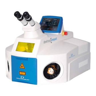
4 Description of the laser system 4.1 Areas of application The laser welding system desktop Compact is a compact tabletop unit with a closed working chamber for the manual laser welding of metal compounds. The laser system is intended for use in workshops and laboratories, e.g., dental laboratories and goldsmith work- shops. -
Page 21: Figure 2 Schematic Representation Of The Laser Beam Path
Figure 2: Schematic representation of the laser beam path Telescope Ocular Output coupler mirror LCD-Shutter (UV and glare shield) Safety shutter Laser protection glass Pump chamber with flash lamp and laser rod Deflection mirror Rear mirror Focusing lens Resonator Protection glass Laser beam Plasma flare Deflection tower... -
Page 22: Overview Of Functionality
Shielding gas, if needed, and the laser pulse are switched on or triggered via a two-stage footswitch. The welding smoke is automatically extracted during and after processing. Figure 3: desktop Compact with open tailboard The elements of the working chamber are described in Figure 5 on page 23. -
Page 23: Laser Head And Microscope Attachment
Figure 4: Overview – Exterior view Key switch (not visible) Emergency button Microscope attachment Ventilation slots extracted air Laser protection window with a view into Ventilation slots supply air the working chamber Lateral sleeve left Lateral sleeve right Tailboard Footswitch Touchscreen 4.4 Laser head and microscope attachment The microscope attachment is used to position the workpiece precisely below the laser beam in the working... -
Page 24: Working Chamber
4.5 Working chamber The working chamber protects the user’s eyes as well as the eyes and skin of other persons from laser radiation. Figure 5: Working chamber Welding fume exhaust Rotary knob for adjusting the shielding gas post-flow time (optional) Fixing screws for filter holder of welding fume exhaust (2x) Flexible shielding gas nozzle Swiveling shielding gas nozzle (height adjustable by turning) -
Page 25: Operating Elements
This section describes the laser system’s individual operating elements. 4.6.1 Key switch See Figure 4 on page 22. Activate the laser system with the key switch on the desktop Compact. This supplies all components of the desktop Compact with power. 4.6.2 Emergency button See Figure 4 on page 22. -
Page 26: Touchscreen
4.6.3 Touchscreen Use the touchscreen to control the laser. Figure 7: Touchscreen See also: Figure 4 on page 22. 4.6.4 Operating elements in the working chamber The working chamber has the following operating elements: Figure 8: Operating elements of the working chamber Joystick for setting the laser parameters Laser power W+, W- and pulse duration ms-, ms+ Joystick for setting the laser parameters pulse frequency Hz+, Hz- and beam diameter Ø-, Ø+ In parameter set selection mode, this joystick is also used to confirm or cancel the selection of a parameter... -
Page 27: Footswitch
4.6.5 Footswitch Use the two-level footswitch to supply shielding gas and trigger laser pulses. See also: Operating the footswitch on page 30. 4.7 External connections and type plate Figure 9 External connections Type plate Shielding gas connection The pressure reducer of the gas cylinder should be adjustable in the range of 1 l /min - 10 l / min. A flow of approximately 3 l / min - 7 l / min is recommended. -
Page 28: Installation And Commissioning
5. Installation and commissioning CAUTION The laser system is dangerous if the operator does not observe the organizational and personal safety measures! Do not switch on the laser system until you have read and understood this instruction manual, especially the chapter on Safety. -
Page 29: Checking The Local Mains Connection
Use the packing list to check the delivery for completeness. The following is included in the scope of delivery of the desktop Compact: · Footswitch · Additionally ordered optional accessories 5.4 Checking the local mains connection Before connecting the laser system to the local power grid, make sure that the local power grid’s supply meets the laser system’s requirements (see Technical data on page 18). -
Page 30: Connecting Power, Components, And Shielding Gas
Compact via the filling tube on the rear side. Empty the coolant container via the filling tube on the back before each transport of the desktop Compact and open the pump chamber for a few seconds. This prevents damage from leaking or freezing coolant. -
Page 31: Operation
If applicable, open the gas cylinder with shielding gas. Turn on the key switch. If you have performed maintenance on the desktop Compact previously (changed flash lamp, filled coolant, etc.), wait approximately five minutes before welding. 6.2 Positioning the workpiece... -
Page 32: Using Shielding Gas
Triggering a laser pulse and supplying shielding gas Requirement: Press the Shutter open button to open the safety shutter. of the buttons Shutter open and Laser OK illuminate. The green displays Press the two-level button of the footswitch until the first level. The shielding gas flows out. -
Page 33: Operating The Touchscreen
6.5 Operating the touchscreen The laser is operated via the touchscreen. The touchscreen is also used to change system settings. After the desktop Compact is started, the touchscreen shows the main window in standard mode: Figure 11 Touchscreen main window – standard mode... -
Page 34: Setting The Laser Parameters
The laser parameters Laser power, pulse duration, and pulse frequency determine the average laser power. The average laser power is limited by the capacity of the desktop Compact. If you increase the Laser power and/or pulse duration, the laser system automatically lowers the pulse frequency as soon as the capacity of the laser system has been reached. -
Page 35: Saving And Loading A Parameter Set
The shape of the pulse is also shown in the diagram. 6.7 Saving and loading a parameter set You can save laser parameters that you use frequently in the desktop Compact database as a parameter set and load them at any time. -
Page 36: Figure 13 Parameter Set Display
Figure 13: Parameter set display Parameter set, saving Press the Save parameter set button . The color of the button arrow turns orange and the two buttons to the left and right of it change their function. They are now used to select the memory location number. The two buttons in the menu bar also change their function: Figure 14: Touchscreen main window –... -
Page 37: Figure 15 Touchscreen Main Window - In Load Parameter Set Mode
Figure 15: Touchscreen main window – in load parameter set mode Press the Minus / Plus buttons / , until the desired memory location is displayed (M01 - M39). The laser parameter values of the respective parameter set are displayed. ... -
Page 38: Opening / Closing The Safety Shutter
Press the Return key , to save the changed description text. Or: Press the Cancel button , to return to standard mode without saving. If neither button is pressed within 3 seconds, the main window will automatically return to normal mode. 6.8 Opening / closing the safety shutter ... -
Page 39: Figure 18 Ocular And Eyecups Of The Leica Microscope Attachment
Figure 18: Ocular and eyecups of the Leica microscope attachment Eyecup with removable protective ring in base position (folded up, without glasses) Eyecup with removable protective ring folded back (for eyeglass wearers) Ocular Diopter ring Tube Fixing screw of the ocular to turn the cross-hair Setting the eye distance ... -
Page 40: Welding
Pull the eyecup upward to the desired height. Hold the diopter ring and tighten the eyecup in the clockwise direction. If you wear glasses: Standard microscope attachment: Fold the eyecup down. Set the oculars to your individual eyesight: ... -
Page 41: Displaying And Changing The Default Settings
· Switch the micro welding feature on and off (Mode Shutter) How to do it: button opens the options menu, which allows you to change the default settings of the desktop Compact and retrieve system values. Press the Settings button... -
Page 42: Setting The Illumination In The Working Chamber
Figure 20: Touchscreen – options menu Return key: For menu items with system value query to update the value. OK is then displayed on the right. Up / Down buttons: To select the menu item. Left / Right buttons: For menu items with numerical values to select the decimal point. Minus / Plus buttons: For menu items with numerical values to change the decimal point. -
Page 43: Switching The Laser System Off
Figure 21: Touchscreen – error message (= interlock) Error message symbol Warning triangle Button for resetting the error message Press the Reset interlock button . The yellow display turns off. See also: Messages and troubleshooting on page 56. 6.14 Switching the laser system off ... -
Page 44: Maintenance
Only trained personnel are to perform the laser system maintenance work described here. Maintenance tasks that are not described in this chapter may only be performed by Dentaurum service engineers. Use only appropriate tools and measuring equipment. -
Page 45: Weekly Inspection
52). 7.3 Opening the laser system Many of the parts requiring maintenance are located in the housing of the laser system. This section covers the opening and closing of the desktop Compact. DANGER Laser radiation and electricity! ... -
Page 46: Figure 23 Microscope Attachment Flange (From Above)
To open the housing, first remove the microscope attachment. Removing the microscope attachment Switch the laser system off. Disconnect the power plug. Wait for at least 5 minutes. Loosen the set screw from the bottom right of the microscope attachment. ... -
Page 47: Reclosing The Housing
Figure 24: Laser system with open housing Guide hook for housing Coolant container Resonator with laser Laser power supply Deflection mirror 7.3.1 Reclosing the housing Close the housing without trapping cables. Retighten the fixing screws and close the locks. ... -
Page 48: Cleaning The Laser System
7.4 Cleaning the laser system Be sure to do the following when cleaning the laser system: Switch off the laser system and unplug the power plug. Wash the laser system on the outside and in the work area with a slightly damp cloth. Do not use harsh cleaning agents. -
Page 49: Checking The Laser Adjustment
Place the photographic paper under the laser objective outside of the laser focal spot. The photographic paper is available from Dentaurum. Set the following laser parameters: 3000 W – 6 ms – 1.0 Hz – 2.0 mm ... -
Page 50: Adjusting The Deflection Mirror And Crosshairs
Figure 24 on page 46 shows the position of the deflection mirror on the desktop Compact. During welding, the laser focal spot, i.e., the welding spot, must be located exactly in the cross-hair. If this is not the case, the focal spot of the laser beam does not correspond to the focal spot of the objective, and the deflection mirror must be readjusted. -
Page 51: Inspecting And Changing The Welding Fume Exhaust Filter
CAUTION Welding smoke is hazardous to health! Wear respiratory protection (with filter class FFP-2) and disposable gloves (available from Dentaurum). Place the filter into a plastic bag immediately and close it firmly. Dispose of the filter as hazardous waste according to your local regulations. -
Page 52: Figure 29 Welding Fume Exhaust In The Working Chamber
a Filter holder fixing screws (2x) b Filter holder of the welding fume exhaust Figure 29: Welding fume exhaust in the working chamber The welding fume exhaust filter consists of the following components: · Metal netting as fire protection · Filter mat for coarse particles (filter class F5 according to DIN EN 779) ·... -
Page 53: Changing Coolant And The Particle Filter
Screw the fixing screws of the filter holder back on. 7.9 Changing coolant and the particle filter The desktop Compact is cooled with approx. 5 liters of deionized water. There is a level sensor in the coolant container that detects whether enough coolant is present. If not, an error message (interlock) is displayed (see Messages and troubleshooting on page 56). -
Page 54: Figure 31 Coolant Container
a Cover b Opening for outflow tube c Particle filter d Level sensor Figure 31: Coolant container You can fill / remove the coolant through the filling tube on the back without opening the housing of the desktop Compact. Figure 32: Empty and fill in coolant Base position –... - Page 55 Filling coolant See Figure 32 on page 53, position C. Fold the filling tube into position C. Remove the screw of the filling tube with a 10 mm Allen wrench. Carefully fill the deionized coolant into the filling tube using a funnel. ...
-
Page 56: Replacing The Fuse
7.10 Replacing the fuse The laser system is fitted with fuses. The fuses are located on the back of the laser system. If overloading occurs, the fuses can be replaced. Figure 33: Replacing the fuses Carry out the following steps for both fuses: ... -
Page 57: Transport, Storage, And Disposal
Avoid high temperature fluctuations; otherwise condensation can form and damage the laser system. (see Ambient conditions on page 27) For long-term storage, empty the coolant container of the desktop Compact (see Changing coolant and the particle filter on page 52). -
Page 58: Error Messages Of The Laser Control
9.1 Error messages of the laser control Symbol Other displays Possible cause Elimination Who? Shutter close button illuminates. The user decreased the value Wait. Customer Shutter open button flashes. of the voltage. To discharge the excess voltage, the laser system activates the flash lamp with closed safety shutter until the adjusted lower value is reached. - Page 59 Shutter close button Automatic flash lamp ignition Change the flash lamp. Trained illuminates. failed. Flash lamp, laser, or customer, Reset Interlock button igniter defective or poor DI service illuminates. water quality. department Laser OK display illuminates red. Laser OK display illuminates Electrical connection to the Trained Press the Reset Interlock button...
-
Page 60: Other Laser Control Errors
9.2 Other laser control errors Message / display Other symptoms Possible cause Elimination Who? Common laser parameters Laser pulse energy Protective glass dirty. Clean or replace the protection Customer appears to be too low glass (see page 47). with the usual settings. Flash lamp old. -
Page 61: Error Codes
9.3 Error codes If an error occurs on the desktop Compact, an error code is displayed in the Error string field of the options menu, which consists of alphanumeric characters (see Displaying and changing the default settings on page 40). -
Page 62: Spare Parts
Stored error Simmer demolition. End of error string. 10. Spare parts The spare parts that can be ordered for the laser system desktop Compact from Dentaurum can be found here. Spare parts ...........................REF Particle filter in the coolant container .................... -
Page 63: Glossary
The electrical conductivity is specified in μS / cm (microSiemens per centimeter) for determining the degree of purity. For Dentaurum laser systems, the purity value must be less than 5 μS / cm. - Page 64 Microscope attachment The microscope attachment serves for positioning the welding spot on the workpiece as well as the optical monitoring of the laser welding process. All Dentaurum laser sys- tems have a stereo microscope attachment with separate laser beam path for each eye.
-
Page 65: Ec Declaration Of Conformity
Directive 2006/42/EC. Description of the machine: The desktop Compact laser is a Class 4 laser welding machine and is intended for the welding of metal connections or cladding of metals. Type:... -
Page 66: Index
Index Direct laser radiation Adjustment, see Laser adjustment, checking Disinfection 13, 47 Air humidity Disposable gloves Ambient conditions Disposal 50, 56 Areas of application EC-Declaration of Conformity Beam outlet Electrical connections · Position on laser system · Technical data Blue light Electrician Burns Electricity, protection against... - Page 67 Gloves, see disposable gloves · Switching on Laser system, cleaning Health hazards Laser system, disposing Housing, opening Laser system, opening Housing, protection class Laser system, setting up Hygiene 13, 47 Laser system, storing Laser warning lamp Illumination Laser welding, basic principles ·...
- Page 68 Operating elements in the working chamber Secondary radiation Operating the laser system Sensor Operator · Level sensor · Laser safety measures Setting up, height · Obligations Setting up, laser system Overview of functionality Shielding gas 12, 20 · Using Pacemaker Shielding gas nozzle Parameter set ·...
- Page 69 UV radiation Ventilation slot · Position on laser system Vibration total value Warning labels Warning notices Water, see Coolant Water tank, see Coolant container Wear parts Weekly maintenance Weight Welding Welding fume exhaust · Position on laser system Welding fumes, see smoke Working chamber ·...
Need help?
Do you have a question about the desktop Compact and is the answer not in the manual?
Questions and answers