DENTAURUM Master 3000 Instructions For Use Manual
Hide thumbs
Also See for Master 3000:
- Instructions for use manual (32 pages) ,
- Instructions for use manual (118 pages)
Table of Contents
Advertisement
Quick Links
Advertisement
Table of Contents

Subscribe to Our Youtube Channel
Related Manuals for DENTAURUM Master 3000


Summary of Contents for DENTAURUM Master 3000
- Page 1 Instructions for use Master 3000 REF 079-000-00...
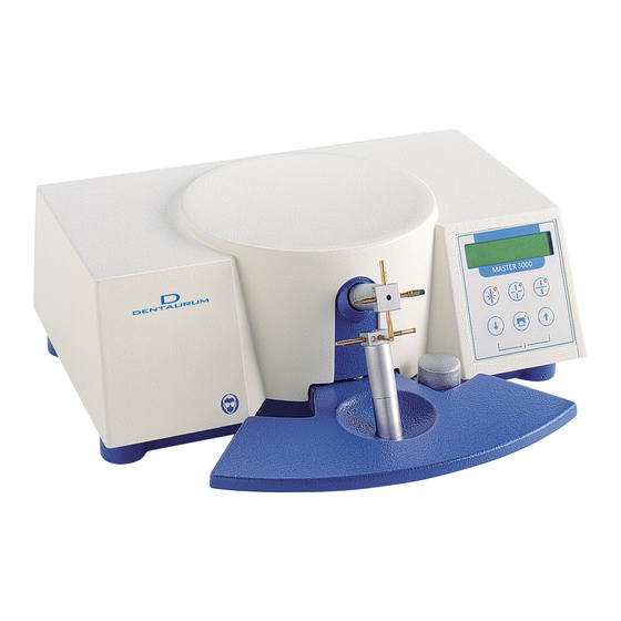
- Page 2 Features and Controls Handrest with electrode opening mechanism Lower click-stop electrode holder Upper click-stop electrode holder Manual button LCD display Pad for selecting “welding” mode Pad for selecting “soldering” mode Pad for selecting “continuous soldering” mode Pad for reducing welding or soldering power Pad for increasing welding or soldering power Pad for triggering printer function...
- Page 3 Outlet for hand electrodes Outlet for hand electrodes Combination outlet for power supply, power plug and fuse holder Outlet for foot switch Outlet for printer (RS-232 interface) Housing with tray...
-
Page 4: Table Of Contents
9.3 Function: Printing in ”soldering” mode ..................... 18 10. Power-saving mode ..........................18 11. Troubleshooting ..........................19 12. Dentaurum Customer Service - Equipment ..................20 13. Care and maintenance ........................20 14. Spare parts for “click-stop“ holders ....................20 15. Optional accessories ........................... 21 15.1 Spare parts for hand electrodes ....................... -
Page 5: Manufacturer
2.1 Intended use The Master 3000 is only intended for welding and soldering of orthodontic appliances. The use of the unit for any other purpose is prohibited. The use of the unit for its correct purpose also includes compliance with all the instructions contained in the Instructions for use „... -
Page 6: Danger Symbols And Markings
Dentaurum Customer Service’s personnel or authorized service technicians. When a Dentaurum product is taken out of operation once and for all, the disposal regulations of the country of operation apply. Dentaurum or the dental trade is available to answer questions regarding the correct disposal of any specific product. -
Page 7: Technical Data
The unit is now ready for operation. 7.1 Setting language of LCD display The Master 3000 is able to display five different languages on the LCD display. These languages are: „ German (manufacturer’s setting) „ English „ French „ Italian „ Spanish... -
Page 8: Operating Instructions
In order to meet the complex requirements for constructing orthodontic appliances, the Master 3000 is fitted with 7 different copper electrodes for welding. These have special contact tips or surfaces. - Page 9 Electrode combinations and designs for welding: for welding: for welding: brackets, tubes, hooks wire to wire wire to bands and loops Upper electrode Upper electrode Upper electrode REF 085–000–00 REF 085–200–00 REF 085–100–00 Lower electrode Lower electrode Lower electrode REF 086–100–00 or REF 086–000–00 REF 086–200–00 REF 086–300–00 For recommended welding settings, see charts (p.
-
Page 10: Spot Welding With "Click-Stop" Electrodes
Spot-welding crossed wires Where the wires are simply crossed, a single spot-weld is usually adequate to connect them properly. In many cases, it is advisable to solder the wires in addition to welding. In this case, please take into account that heating the wires when soldering them to strengthen the joint also causes the mechanical properties of the wires to deteriorate. -
Page 11: Spot Welding With Hand Electrodes (Optional Accessory)
8.1.2 Spot welding with hand electrodes (optional accessory) This process is recommended when for example wires have to be fixed against one another on the model. The components removed from the model should then be re-welded or soldered at the click-stop electrodes. -
Page 12: Soldering
Recommended accessory: Connect foot switch REF 080-116-00 to outlet 8.2 Soldering When soldering, always wear safety goggles. If soldering takes too long, the soldering carbon will be damaged. When using hand electrodes for soldering or heat-treating, the electrodes must not touch each other at the electrode holders. -
Page 13: Soldering With "Click-Stop" Electrodes
8.2.1 Soldering with the click-stop electrodes First tack weld the parts together with a weld spot. Procedure 1. Turn power switch to position “I”. The previously selected mode appears again. 2. Press pad to select the “soldering” mode. The LCD display now shows “soldering” and the last figure set for soldering energy, e. -
Page 14: Soldering With Hand Electrodes (Optional Accessory)
8.2.2 Soldering with hand electrodes (optional accessory) Procedure 1. Turn the upper electrode head on the click-stop holder one turn (45°) to the left or the right. The upper and lower electrodes must not touch each other. 2. Push the plugs of the hand electrodes into the outlets 3. -
Page 15: Heat Treatment
8.3 Heat treatment 8.3.1 Annealing of wires Spring hard chrome nickel stainless steel wires (e. g. remanium ) can be soft annealed at a ® temperature of approx. 1100 °C / 2012 °F (heat color: bright red). Soft annealed CoCr wires cannot be tempered (hardened)! Complex bending operations (especially around tight radii with thick wires, e. -
Page 16: Stress Relieving Of Wires
8.3.3 Stress relieving of wires When spring hard wires are bent, stresses are created in their crystalline structure. The bent wire element can be stress relieved using a suitable heat treatment process. This is done by heating the wire to approx. 550 °C / 1022 °F over a short period of time. (Heat color: dark red). Remember that stress relieving wire elements on the model takes longer as the plaster absorbs a considerable amount of heat. -
Page 17: Printer Function/Report Printing
Note: To soft anneal thick wires, we recommend placing these on a conductive, heat-resistant „ „ base, e.g. a graphite slab. Instead of the notched electrode REF 081-501-00, the clamping electrode REF 081-701-00 „ „ in a hand electrode can be used to hold the wire element. To practice the techniques necessary for soft annealing, tempering and stress relieving, we „... -
Page 18: Function: Printing In "Soldering" Mode
9.3 Function: Printing in “solder” mode 1. Connect the printer to the welding unit as described in section 9.1. 2. Press pad on the welding unit to select “soldering“ mode. The LCD display now shows “soldering” and the last figure set, e. g. 50. 3. -
Page 19: Troubleshooting
The unit operates under high voltage! To prevent accidents, never open the unit. If malfunctions cannot be corrected in the above ways, please contact Dentaurum Customer Service (see page 20). *Replacing the fuse: Unlock the fuse insert on the right-hand side of the combination plug and pull it out. -
Page 20: Dentaurum Customer Service - Equipment
Dentaurum GmbH & Co. KG I Turnstr. 31 I 75228 Ispringen I Germany (P.O.B. 100 440, 75104 Pforzheim) Tel. + 49 72 31 / 803-211 I Fax + 49 72 31 / 803-295 I info@dentaurum.com 13. Care and maintenance The unit requires no maintenance. -
Page 21: Optional Accessories
15. Optional accessories Foot or knee switch, combined Holder for hand electrode REF 080–116–00 REF 081-204–00 1 piece 1 pair REF 081-205–00 Holder, right REF 081-206–00 Holder, left Hand electrode, single Report printer REF 081-101–00 REF 090-581-00 1 piece 1 piece 15.1 Spare parts for hand electrodes Soldering carbon Electrodes, notched with copper jacket for hand electrode... -
Page 22: Installation Of The Holder For Hand Electrodes
15.2 Installation of the holder for hand electrodes REF 081-204-00 / 081-205-00 / 081-206-00 Tools required: Phillips screwdriver Turn the welding unit upside down. Do not place the welding unit on top of the electrodes. Installation of the electrode holder. Connect the hand electrodes and place them into the holder. -
Page 23: Schematic
16. Schematic... - Page 24 No. – Description ........................1 – Fuse 3.15 At 230 V ..................REF 907-037-10 2 – Unit base (no image) ................... REF 908-868-00 3 – Power cable (no image) ................REF 907-027-10 4 – Control board .................... REF 908-895-10 5 – Power board ....................REF 908-895-00 6 –...
-
Page 25: Welding Charts
17.1 Noninium wires ® Material 1 Material 2 Electrode Setting Setting Setting combination Junior 3000 Assistent 3000 Master 3000 Noninium wire Noninium wire REF 085-200-00 ® ® 0.7 mm hard 0.7 mm hard Stage 2 Stage 3 – 4 46 – 48 REF 520-070-00... -
Page 26: Remanium ® Wires
17.2 remanium wires ® Material 1 Material 2 Electrode Setting Setting Setting combination Junior 3000 Assistent 3000 Master 3000 remanium wire remanium wire REF 085-200-00 ® ® Stage 2 0.7 mm hard 0.7 mm hard Stage 5 59 – 61 tack welding REF 513-070-00... -
Page 27: Remaloy ® Wires
17.3 remaloy wires ® Material 1 Material 2 Electrode Setting Setting Setting combination Junior 3000 Assistent 3000 Master 3000 REF 085-200-00 Stage 2 Stage 3 – 4 35 – 40 remaloy wire remaloy wire ® ® REF 086-100-00 0.7 mm hard 0.8 mm hard REF 528-070-00... -
Page 28: Rematitan ® Special Wires
17.4 rematitan SPECIAL wires ® Material 1 Material 2 Electrode Setting Setting Setting combination Junior 3000 Assistent 3000 Master 3000 rematitan SPECIAL rematitan SPECIAL ® ® REF 085-200-00 wire wire Stage 1 Stage 1 8 – 10 0.4 mm 0.4 mm REF 086-300-00... -
Page 29: Other Materials
17.5 Other materials Material 1 Material 2 Electrode Setting Setting Setting combination Junior 3000 Assistent 3000 Master 3000 Standard biscup Stage 5 78 – 80 bands tack welding tack welding REF 860-012-00 hyrax II 12/10 Hand electrodes ® REF 602-808-00 REF 081-501-00 Dentadorm Snap ®... -
Page 30: Quality Information
18. Quality information Dentaurum ensures a faultless quality of the products manufactured by us. These recommendations are based upon our own experiences. The user is responsible for the processing of the products. Responsibility for failures cannot be taken, as we have no influence on the processing on site. -
Page 31: Ec-Declaration Of Conformity
EC-Declaration of Conformity DENTAURUM GmbH & Co. KG Turnstr. 31 75228 Ispringen hereby declares that the design and construction of the laboratory equipment described below, including the version marketed by us, comply with the basic regulations governing safety and health as stated in the EC Guidelines. This declaration will become invalid if the laboratory equipment is modified or altered in any way without our prior consent. - Page 32 Â „ For more information on our products and services, please visit www.dentaurum.com Date of information: 06/18 Subject to modifications Turnstr. 31 I 75228 Ispringen I Germany I Phone + 49 72 31 / 803 - 0 I Fax + 49 72 31 / 803 - 295...
Need help?
Do you have a question about the Master 3000 and is the answer not in the manual?
Questions and answers