Table of Contents
Advertisement
Quick Links
IMPORTANT INFORMATION ABOUT LEAD FREE, (PbF), SOLDERING
If lead free solder was used in the manufacture of this product the printed circuit boards will be marked PbF.
Standard leaded, (Pb), solder can be used as usual on boards without the PbF mark.
When this mark does appear please read and follow the special instructions described in this manual on the use of PbF and how
it might be permissible to use Pb solder during service and repair work.
KX-TDA0103XJ
KX-TDA0104XJ
KX-TDA0108XJ
KX-TDA0103X
KX-TDA0104X
KX-TDA0108X
(for Asia, Oceania, Middle Near East, Africa, Latin
America and Europe)
© 2003 Panasonic Communications Co., Ltd. All
rights
reserved.
distribution is a violation of law.
ORDER NO. KMS0303680C8
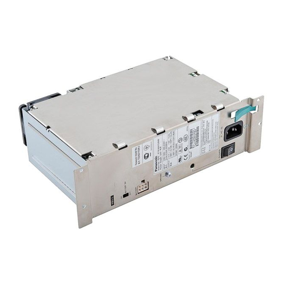
Power Supply Unit
Unauthorized
copying
and
Advertisement
Table of Contents
Troubleshooting

Related Manuals for Panasonic KX-TDA0104


Summarization of Contents
1 ABOUT LEAD FREE SOLDER (PbF: Pb free)
1.1. SUGGESTED PbF SOLDER
Recommended types and sizes of lead-free solder for service.
3 CAUTION
3.1. NOTE
Instruction to record the 11-digit serial number.
3.2. SAFETY PRECAUTIONS
Refers to other manuals for safety guidelines.
3.3. INSULATION RESISTANCE TEST
Refers to other manuals for insulation test procedures.
3.4. CAUTION
Notes on the accessibility of the power outlet.
4 SPECIFICATIONS
4.1. GENERAL DESCRIPTION
Overview of input/output characteristics for each PSU model.
4.2. SYSTEM CAPACITY
PSU selection based on load figures and system configuration.
4.2.1. Power Supply Unit Selection
Guidance on calculating load figures and choosing the right PSU.
5 INSTALLATION
5.1. INSTALLING/REPLACING THE POWER SUPPLY UNIT
General steps for PSU installation and replacement.
5.1.1. Function
Describes the main functions and input ranges of PSUs.
Safety Instructions
Essential safety precautions during installation.
5.1.2. Installing the Power Supply Unit
Step-by-step guide for physically installing the PSU.
5.1.3. Replacing the Power Supply Unit
Step-by-step guide for replacing an existing PSU.
6 DISASSEMBLY INSTRUCTIONS
6.1. PSU-S (KX-TDA0108XJ/X)
Disassembly steps for the S-type PSU.
6.2. PSU-M (KX-TDA0104XJ/X)
Disassembly steps for the M-type PSU.
6.3. PSU-L (KX-TDA0103XJ/X)
Disassembly steps for the L-type PSU.
7 POWER SUPPLY UNIT CIRCUIT OPERATION
7.1. PSU-S (KX-TDA0108XJ/X)
Details the PSU-S structure and block diagram.
7.1.1. Block Diagram of PSU-S
Schematic overview of the PSU-S internal circuitry.
7.2. CIRCUIT DESCRIPTION
Explains the circuits within the PSU.
7.2.1. APFC Converter
Description of the Active PFC converter circuit.
7.2.2. Main Converter
Description of the main DC-DC converter circuit.
7.2.3. Stepdown Converter (40V → 30V)
Description of the stepdown converter for 30V output.
7.2.4. Stepdown Converter (40V → 15V)
Description of the stepdown converter for 15V output.
7.2.5. 15VPT Control Circuit
Description of the circuit controlling the +15VPT output.
7.2.6. Backup Batteries Charge Function
Explanation of the battery charging mechanism.
7.2.7. AC Cutoff Detection Function
How AC power failure is detected and signaled.
7.2.8. DC Abnormality Detection Function
How DC output abnormalities are detected and signaled.
7.2.9. Overheating Detection Function
How overheating is detected and handled.
7.3. PSU-M (KX-TDA0104XJ/X)
Details the PSU-M structure and block diagram.
7.3.1. Block Diagram of PSU-M
Schematic overview of the PSU-M internal circuitry.
7.4. CIRCUIT DESCRIPTION
Explains the circuits within the PSU-M.
7.4.1. APFC Converter
Description of the Active PFC converter circuit in PSU-M.
7.4.2. Main Converter
Description of the main DC-DC converter circuit in PSU-M.
7.4.3. Stepdown Converter (40V → 30V)
Description of the 30V stepdown converter in PSU-M.
7.4.4. Stepdown Converter (40V → 15V)
Description of the 15V stepdown converter in PSU-M.
7.4.5. 15VPT Control Circuit
Description of the +15VPT control circuit in PSU-M.
7.4.6. Backup Batteries Charge Function
Explanation of the battery charging mechanism in PSU-M.
7.4.7. AC Cutoff Detection Function
How AC power failure is detected in PSU-M.
7.4.8. DC Abnormality Detection Function
How DC output abnormalities are detected in PSU-M.
7.4.9. Overheating Detection Function
How overheating is detected in PSU-M.
7.5. PSU-L (KX-TDA0103XJ/X)
Details the PSU-L structure and block diagram.
7.5.1. Block Diagram of PSU-L
Schematic overview of the PSU-L internal circuitry.
7.6. CIRCUIT DESCRIPTION
Explains the circuits within the PSU-L.
7.6.1. APFC Converter
Description of the Active PFC converter circuit in PSU-L.
7.6.2. Main Converter
Description of the main DC-DC converter circuit in PSU-L.
7.6.3. Stepdown Converter (40V → 30V)
Description of the 30V stepdown converter in PSU-L.
7.6.4. Stepdown Converter (40V → 15V)
Description of the 15V stepdown converter in PSU-L.
7.6.5. 15VPT Control Circuit
Description of the +15VPT control circuit in PSU-L.
7.6.6. Backup Batteries Charge Function
Explanation of the battery charging mechanism in PSU-L.
7.6.7. AC Cutoff Detection Function
How AC power failure is detected in PSU-L.
7.6.8. DC Abnormality Detection Function
How DC output abnormalities are detected in PSU-L.
7.6.9. Overheating Detection Function
How overheating is detected in PSU-L.
8 TROUBLESHOOTING GUIDE
8.1. KX-TDA0108XJ/X POWER UNIT TROUBLE SHOOTING
Specific troubleshooting steps for the KX-TDA0108XJ/X PSU.
8.1.1. No Voltages are Output at All
Troubleshooting when no output voltages are detected.
8.1.2. +41V, +30V, +15VPT are Not Output (Only +15V is Output)
Troubleshooting when specific voltages are missing.
8.1.3. Only +41V is Not Output
Troubleshooting when only +41V is absent.
8.1.4. Only +30V is Not Output
Troubleshooting when only +30V is absent.
8.1.5. Only +15VPT is Not Output
Troubleshooting when only +15VPT is absent.
8.1.6. Only +41V is Available (Other Voltage are Not Output)
Troubleshooting when +41V is present but others are not.
8.1.7. Battery Backup Function does Not Operate / PSU can Not Charge Batteries
Troubleshooting battery backup and charging issues.
8.1.8. AC Alarm is Sent (Although AC Power is Normal)
Troubleshooting AC alarm conditions.
8.1.9. DC Alarm is Sent (Although All DC Output are Normal)
Troubleshooting DC alarm conditions.
8.2. KX-TDA0104XJ/X POWER UNIT TROUBLE SHOOTING
Specific troubleshooting steps for the KX-TDA0104XJ/X PSU.
8.2.1. No Voltages are Output at All
Troubleshooting when no output voltages are detected.
8.2.2. +41V, +30V, +15VPT are Not Output (Only +15V is Output)
Troubleshooting when specific voltages are missing.
8.2.3. Only +41V is Not Output
Troubleshooting when only +41V is absent.
8.2.4. Only +30V is Not Output
Troubleshooting when only +30V is absent.
8.2.5. Only +15VPT is Not Output
Troubleshooting when only +15VPT is absent.
8.2.6. Only +41V is Available (Other Voltage are Not Output)
Troubleshooting when +41V is present but others are not.
8.2.7. Battery Backup Function Does Not Operate / PSU can Not Charge Batteries
Troubleshooting battery issues for PSU-M.
8.2.8. AC Alarm is Sent (Although AC Power is Normal)
Troubleshooting AC alarm conditions for PSU-M.
8.2.9. DC Alarm is Sent (Although All DC Output are Normal)
Troubleshooting DC alarm conditions for PSU-M.
8.3. KX-TDA0103XJ/X POWER UNIT TROUBLE SHOOTING
Specific troubleshooting steps for the KX-TDA0103XJ/X PSU.
8.3.1. No Voltages are Output at All
Troubleshooting when no output voltages are detected.
8.3.2. +41V, +30V, +15VPT are Not Output (Only +15V is Output)
Troubleshooting when specific voltages are missing.
8.3.3. Only +41V is Not Output
Troubleshooting when only +41V is absent.
8.3.4. Only +30V is Not Output
Troubleshooting when only +30V is absent.
8.3.5. Only +15VPT is Not Output
Troubleshooting when only +15VPT is absent.
8.3.6. Only +41V is Available (Other Voltage are Not Output)
Troubleshooting when +41V is present but others are not.
8.3.7. Battery Backup Function does Not Operate / PSU can Not Charge Batteries
Troubleshooting battery issues for PSU-L.
8.3.8. AC Alarm is Sent (Although AC Power is Normal)
Troubleshooting AC alarm conditions for PSU-L.
8.3.9. DC Alarm is Sent (Although All DC Output are Normal)
Troubleshooting DC alarm conditions for PSU-L.
8.3.10. Cooling Fan Trouble
Troubleshooting issues related to the cooling fan.
9 HOW TO REPLACE A FLAT PACKAGE IC
9.1. PREPARATION
Required tools and materials for IC replacement.
9.2. PROCEDURE
Steps for tack soldering and applying flux to IC pins.
9.3. REMOVING SOLDER FROM BETWEEN PINS
Method for removing solder bridges between IC pins.
10 CABINET AND ELECTRICAL PARTS LOCATION
10.1. PSU-S (KX-TDA0108XJ/X)
Component layout for the PSU-S model.
10.2. PSU-M (KX-TDA0104XJ/X)
Component layout for the PSU-M model.
10.3. PSU-L (KX-TDA0103XJ/X)
Component layout for the PSU-L model.
10.4. SCREWS AND WASHER
Details of screws and washers used in assembly.
10.5. EXTENSION CORD FOR SERVICING
Information on extension cords for servicing.
11 ACCESSORIES AND PACKING MATERIALS
11.1. PSU-S (KX-TDA0108XJ/X)
Accessories and packing for PSU-S.
11.2. PSU-M (KX-TDA0104XJ/X)
Accessories and packing for PSU-M.
11.3. PSU-L (KX-TDA0103XJ/X)
Accessories and packing for PSU-L.
12 REPLACEMENT PARTS LIST
12.1. KX-TDA0108XJ/X
Replacement parts specific to the KX-TDA0108XJ/X model.
12.1.1. Electrical Parts
List of electrical components and their part numbers.
12.1.2. Accessories and Packing Materials
List of accessories and packing items.
12.1.3. Main Board Parts
List of parts located on the main board.
12.2. KX-TDA0104XJ/X
Replacement parts specific to the KX-TDA0104XJ/X model.
12.2.1. Electrical Parts
List of electrical components and their part numbers for PSU-M.
12.2.2. Accessories and Packing Materials
Accessories and packing for PSU-M.
12.2.3. Main Board Parts
List of parts on the main board of PSU-M.
12.2.4. Filter/Battery Board Parts
List of parts for the filter/battery board of PSU-M.
12.3. KX-TDA0103XJ/X
Replacement parts specific to the KX-TDA0103XJ/X model.
12.3.1. Electrical Parts
List of electrical components and their part numbers for PSU-L.
12.3.2. Accessories and Packing Materials
Accessories and packing for PSU-L.
12.3.3. Main Board Parts
List of parts on the main board of PSU-L.
12.4. FIXTURES AND TOOLS
List of special fixtures and tools for servicing.
14 SCHEMATIC DIAGRAM
14.1. S-TYPE POWER SUPPLY UNIT (PSU-S) / KX-TDA0108XJ/X
Schematic diagram for the S-type PSU.
14.2. M-TYPE POWER SUPPLY UNIT (PSU-M) / KX-TDA0104XJ/X
Schematic diagram for the M-type PSU.
14.3. L-TYPE POWER SUPPLY UNIT (PSU-L) / KX-TDA0103XJ/X
Schematic diagram for the L-type PSU.
15 PRINTED CIRCUIT BOARD
15.1. S-TYPE POWER SUPPLY UNIT (PSU-S) / KX-TDA0108XJ/X
Component placement diagram for the S-type PSU PCB.
15.2. M-TYPE POWER SUPPLY UNIT (PSU-M) / KX-TDA0104XJ/X
Component placement diagram for the M-type PSU PCB.
15.3. L-TYPE POWER SUPPLY UNIT (PSU-L) / KX-TDA0103XJ/X
Component placement diagram for the L-type PSU PCB.
Need help?
Do you have a question about the KX-TDA0104 and is the answer not in the manual?
Questions and answers