
Related Manuals for Kyoritsu Electrical Instruments Works 4105A


Summary of Contents for Kyoritsu Electrical Instruments Works 4105A
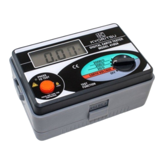
- Page 1 INSTRUCTION MANUAL Digital Earth Resistance Tester MODEL 4105A KYORITSU ELECTRICAL INSTRUMENTS WORKS, LTD.
-
Page 2: Table Of Contents
CONTENTS 1. Safety Precautions …………………………………………………………… 1 2. Features ………………………………………………………………………… 4 3. Specifications …………………………………………………………………… 5 4. Layout Diagram ………………………………………………………………… 8 5. Preparation for Measurement ………………………………………………… 9 5-1 Battery Voltage Check …………………………………………………… 9 5-2 Connecting Test Probes ………………………………………………… 9 6. Operating Instructions ………………………………………………………… 9 6-1 Principle of Measurement ………………………………………………... -
Page 3: Safety Precautions
1. Safty Precautions The instrument is designed, manufactured, tested and shipped in prime condition in accordance with the following standards. IEC 61010-1 Overvoltage CAT III 300V Pollution Degree 2 IEC 61010-2-31 IEC 61557-1,5 IEC 60529 (IP54) This instruction manual contains warnings and safety rules which must be observed by the user to ensure safety operation of the instrument and to retain it in safe condition. - Page 4 DANGER is reserved for conditions and actions that are likely to cause serious or fatal injury. WARNING is reserved for conditions and actions that can cause serious or fatal injury. CAUTION is reserved for conditions and actions that can cause minor injury or instrument damage.
- Page 5 CAUTION Make sure that the test probe are securely connected to the terminal of the instrument. Be sure to set the range selector switch to the OFF position after use. When the instrument will not be in use for a long period of time, place it in storage after removing the batteries.
-
Page 6: Features
2. Features MODEL 4105A is an earth resistance tester for testing power distribution lines, in-house wiring system, electrical appliances etc. It also has an earth voltage range for earth voltage measurement. Designed to safety standard IEC 61557. Dust and drip proof construction in conformity with IEC 60529 (IP54). -
Page 7: Specifications
3. Specifications Measuring Range and Accuracy (at 23 5°C and RH 75% or less) Range Measuring Range Accuracy Earth Voltage 0 - 199.9V 1.0% rdg 4 dgt 2.0% rdg 0.1Ω( 0 - 19.99Ω ) 20Ω 0 - 19.99Ω Earth 2.0% rdg 3 dgt( above 20Ω... - Page 8 Maximum Operating Error Operating error (B) is an error obtained within the rated operating conditions, and calculated with the intrinsic error (A), which is an error of the instrument used, and the error (Ei) due to variations. A : Intrinsic error : Variation due to changing the position : Variation due to changing the supply voltage : Variation due to changing the temperature...
- Page 9 Power Source 9V DC : R6P (SUM-3) x6 Overload Protection Earth resistance ranges : 280V AC/DC (10 seconds) Earth voltage range : 300V AC/DC (1 minute) Insulation Resistance 5MΩ or more at 500V between the electrical circuit and the housing case Withstand Voltage 3700V AC for one minute between the electrical circuit and the housing case...
-
Page 10: Layout Diagram
4. Layout Diagram q LCD Display w Battery Replacement Mark e Indication LED With qq(Low Battery Symbol) qqMeasurement(Green) r Press To Test Button t Range Selector Switch y Measuring Terminals u Test Leads i Auxiliary Earth Spikes o Simplified Measurement Probe !0 Safety Alligator Clip !1 Test Bar ---- 8 ----... -
Page 11: Preparation For Measurement
5. Preparation for Measurement 5-1 Battery Voltage Check Turn on the instrument. If the display is clear without low battery symbol " " showing, battery voltage is sufficient. If the display blanks or " " is indicated, replace the batteries according to section 7 for Battery Replacement. -
Page 12: Precise Measurement
6-2 Precise Measurement (with Test Probe M-7095) q Test probe connection Stick the auxiliary earth spikes P and C into the ground deeply. They should be aligned at an interval of 5-10m from the earthed equipment under test. Connect the green wire to the earthed equipment under test, the yellow wire to the auxiliary earth spike P and the red wire to the auxiliary earth spike C from terminals E, P and C of the instrument in order. -
Page 13: Simplified Measurement
20Ω when the earth resistance is low. This indicated value is the earth resistance of the earthed equipment under test. Note : If the auxiliary earth resistance of auxiliary earth spike C is too high to make measurement, the display reads ' . . . '. Recheck the connection of test leads and the earth resistance of auxiliary earth spike. - Page 14 Note : When the simplified measurement probes are not used, short P and C terminals. DANGER Please be sure to use a voltage detector to check a common earth of commercial power supply. Do not use the instrument to check a common earth of commercial power supply.
- Page 15 w Earth Voltage Measurement Set the range switch to EARTH VOLTAGE position in the condition of q . Earth voltage will be indicated on the display. Make sure that the voltage is 10V or less. When the display reads more than 10V, it may result in excessive errors in earth resistance measurement.
-
Page 16: Battery Replacement
7. Battery Replacement DANGER Never attempt to open the battery compartment cover, if the outer surface of the instrument is wet. Never attempt to replace batteries while making measurement. To avoid shock hazard, turn the instrument off and disconnect the test leads and the probes from the instrument before opening the battery compartment cover. -
Page 17: Notes On Housing Case & Accessories
8. Notes on Housing Case & Accessories 8-1 Case Lid Case lid can be fit under the housing case while making measurement. 8-2 How to Fit Strap Belt The instrument is equipped with a strap belt to suspend from the neck to allow both hands to be used freely for easy and safe operation ---- 15 ----... -
Page 18: Before Sending For Service
9. Before Sending for Service If this instrument should fail to operate correctly, return it to your nearest distributor stating the exact nature of the fault. Before returning the instrument follow the trouble-shooting guide shown below. If the instrument does not turn on; Check whether batteries are missing or they are installed incorrect polarity. -
Page 19: Service
10. Service If this instrument should fail to operate correctly, return to your nearest distributors stating the exact nature of the fault. ---- 17 ----...
Need help?
Do you have a question about the 4105A and is the answer not in the manual?
Questions and answers