
Related Manuals for Kyoritsu Electrical Instruments Works 3005A


Summary of Contents for Kyoritsu Electrical Instruments Works 3005A
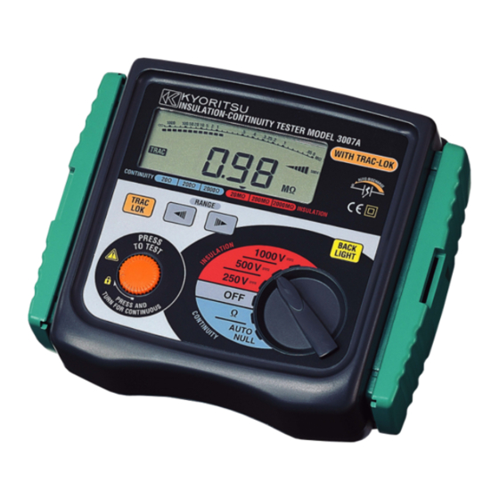
- Page 1 INSTRUCTION MANUAL DIGITAL INSULATION/CONTINUITY TESTER MODEL 3005A/3007A KYORITSU ELECTRICAL INSTRUMENTS WORKS, LTD., TOKYO JAPAN...
-
Page 2: Table Of Contents
CONTENTS 1. SAFETY WARNINGS ··············································································· 1 2. FEATURES ···························································································· 5 3. SPECIFICATIONS ··················································································· 6 4. INSTRUMENT LAYOUT ··········································································· 9 4-1 Instrument layout ············································································ 9 4-2 LCD ····························································································· 10 5. PREPARATION FOR MEASUREMENT ······················································ 12 5-1 Removing the Cover ······································································ 12 5-2 Battery Voltage Check ···································································... -
Page 3: Safety Warnings
1. SAFETY WARNINGS This instrument has been designed, manufactured and tested according to IEC 61010: Safety requirements for Electronic measuring apparatus, and delivered in the best condition after passed the inspection. This instruction manual contains warnings and safety rules which must be observed by the user to ensure safe operation of the instrument and retain it in safe condition. - Page 4 Please refer to following explanation of the symbols used on the instrument and in this manual. Refer to the instructions in the manual. This symbol is marked where the user must refer to the instruction manual so as not to cause personal injury or instrument damage. ...
- Page 5 WARNING ● Never attempt to make any measurement, if the instrument has any structural abnormality such as cracked case or exposed metal parts. ● Stop using the test lead if the outer jacket is damaged and the inner metal or color jacket is exposed. ●...
- Page 6 Measurement categories (Over-voltage categories) To ensure safe operation of measuring instruments, IEC 61010 establishes safety standards for various electrical environments, categorized as O to CAT IV, and called measurement categories. Higher-numbered categories correspond to electrical environments with greater momentary energy, so a measuring instrument designed for CAT III environments can endure greater momentary energy than one designed for CAT II.
-
Page 7: Features
2. FEATURES MODEL-3005A/3007A are microprocessor controlled insulation-continuity testers. ● Designed to safety standards: IEC 61010-1, 61010-2-030 Measurement CAT III 300V Pollution Degree 2 IEC 61010-031 IEC 61557-1,2,4,10 ● Display with back light function to facilitate work at night or dimly lit locations (Model 3007A only) ●... -
Page 8: Specifications
3. SPECIFICATIONS ● Measuring Range and Accuracy (at 23±5°C, relative humidity 45 -75%) ○ Insulation Resistance Ranges: Nominal Output Voltage 250V 500V 1000V 0 ~ 19.99MΩ 0 ~ 19.99MΩ 0 ~ 19.99MΩ Measuring 0 ~ 199.9MΩ 0 ~ 199.9MΩ 0 ~ 199.9MΩ Ranges 0 ~ 1999MΩ... - Page 9 ● Typical Number of Measurements. (central tendency for supply voltage up to 8V) Insulation Resistance Ranges: Approx. 1000 times min. at load 0.5MΩ Continuity Ranges: Approx. 700 times min. at load 1Ω ● Operating instrumental uncertainty (IEC 61557-2,-4) Measuring range to keep Maximum percentage Functions...
- Page 10 ● Dimensions: 185(L) x 167(W) x 89(D) mm approx. ● Weight: 990g approx. (including batteries 3007A) 970g approx. (including batteries 3005A) ● Power Source: 8 x R6P, 1.5V AA or equivalent ● Auto-power-off Function: Automatically turns off approx. 10 minutes after the last switch operation.
-
Page 11: Instrument Layout
4. INSTRUMENT LAYOUT 4-1 INSTRUMENT LAYOUT ⑩ ⑨ ⑧ ①… LCD DISPLAY ②… TRAC-LOKSWITCH (Model 3007A only) ③… RANGE SELECTOR SWITCH ④… TEST BUTTON ⑤… CONNECTOR ⑥… BACK LIGHT SWITCH (Model 3007A only) ⑦… FUNCTION SWITCH ⑧… TEST PROBE (RED) ⑨… TEST PROBE (BLACK) ⑩… ALLIGATOR CLIP (BLACK) ⑪… PROBE (BLACK & RED) ⑫… PROTECTIVE FINGERGUARD Note: It is a part providing protection against electrical shock and ensuring the minimum required air and creepage distances. -
Page 12: Lcd
Protective fingerguard Protective fingerguard: It is a part providing protection against electrical shock and ensuring the minimum required air and creepage distances. Cap: Uncapped condition for CAT II environment Capped condition for CAT III/ IV environments The Cap should be firmly attached to the probes. 4-2 LCD DISPLAY —... - Page 13 1… INSULATION RESISTANCE SCALE 2… BAR GRAPH 3… CONTINUITY SCALE 4… LIVE CIRCUIT WARNING AC LIVE CIRCUIT DISCHARGE VOLTAGE WARNING 0~2V 0~2V 3~30V 3~60V 31~60V 61~120V 61~120V 121~240V 120V over 240V over 5… TRACK/LOK MODE 6… AUTONULL OPERATION 7… BATTERY VOLTAGE WARNING 8…...
-
Page 14: Preparation For Measurement
5. PREPARATION FOR MEASUREMENT 5-1 Removing the Cover Model 3005A/3007A have a dedicated cover to protect against an impact from the outside and prevent the operation part, LCD, and connector socket from becoming dirty. The cover can be detached and put on the back side of the main body during measurement. -
Page 15: Operation
6. OPERATION 6-1 Disconnection and check of power source of the circuit under test DANGER ● To avoid possible electrical shock, do not perform measurements on energized (LIVE) circuits. ● Never open the battery compartment cover when making measurement. ● Verify proper operation on a known source before use or taking action as a result indication of the instrument. -
Page 16: Insulation Resistance Measurement
6-2 Insulation Resistance Measurement DANGER ● Always test the circuit or equipment to ensure it is surely de-energized before measurement according to the instruction of 6-1. ● To avoid electrical shock, measurements must be performed on de-energized circuits only. ● When the test button is pressed with the function switch in the MΩ position, take care not to touch the tip of the test probe and the circuit under test where a high voltage is present in order to avoid possible shock hazard. - Page 17 ④ Read the resistance value from the LCD. ⑤ With the test probe still connected to the circuit under test, release the test button to discharge capacitance in the circuit after measurement. DANGER Do not touch the circuit under test immediately after testing. Capacitance stored in the circuit may cause electric shock.
-
Page 18: Continuity Measurement (Resistance Tests)
● Terminal connection of insulation resistance test In case of testing insulation of insulated wire and cable against the earth at direct current, connecting – pole of power to cable conductor, + to the earth obtains smaller measuring value, compared with connecting the other way round. -
Page 19: Continuous Measurement
● Principle of Continuity Measurement (Resistance Test) Resistance value can be obtained by applying a certain current to the resistance under test and measuring the voltage generated on the both sides of the resistor under test. Resistance value = Voltage / Current LINE(+) EARTH(-) 6-4 Continuous Measurement... -
Page 20: Functions
7. FUNCTIONS 7-1 TRAC-LOK MODE (Model 3007A) TRAC mode : Measurement can be conducted while the test button is being pressed. When making continuous measurement, select this mode. LOK mode : When the test button is pressed, measurement can be conducted only once, and output is stopped, then automatically discharged. -
Page 21: Battery & Fuse Replacement
8. BATTERY & FUSE REPLACEMENT DANGER ● Never open the battery compartment cover when making measurement. Ensure that the Test Lead is disconnected from the object under test, and that the instrument is powered off when opening the battery compartment cover for battery or fuse replacement. -
Page 22: Case And Strap Belt Assembly
9. CASE AND STRAP BELT ASSEMBLY By hanging the instrument around the neck, both hands can be used freely for easy and safety working. Pass the strap belt down through the side panel of the main body from the top, and up through the slots of the probe case from the bottom. -
Page 23: Cleaning Of The Instrument
10. CLEANING OF THE INSTRUMENT ● When cleaning the instrument, wipe it with a silicon cloth or soft cloth to remove dust or dirt. ● When it is hard to remove the dirt, wipe it with a cloth wet with water and dry the instrument completely after cleaning. - Page 24 DISTRIBUTOR Kyoritsu reserves the rights to change specifications or designs described in this manual without notice and without obligations. 5-18 92-1492E...
Need help?
Do you have a question about the 3005A and is the answer not in the manual?
Questions and answers