Table of Contents
Advertisement
Quick Links
Advertisement
Table of Contents

Related Manuals for Kyoritsu Electrical Instruments Works 3132A


Summary of Contents for Kyoritsu Electrical Instruments Works 3132A
- Page 1 INSTRUCTION MANUAL ANALOGUE INSULATION-CONTINUITY TESTER MODEL 3132A...
-
Page 2: Table Of Contents
CONTENTS 1. Safety warning ················································································· 1 2. Features ·························································································· 5 3. Specifications ·················································································· 6 4. Instrument Layout············································································· 9 5. Preparation for measurement ·························································· 11 5-1 Mechanical Zero Adjustment ···················································· 11 5-2 Battery Voltage Check ····························································· 11 5-3 Test Probe Connection ···························································· 11 5-4 Test Probe check ····································································... -
Page 3: Safety Warning
1. Safety warnings This instrument has been designed, manufactured and tested according to IEC 61010: Safety requirements for Electronic measuring apparatus, and delivered in the best condition after passed the inspection. This instruction manual contains warnings and safety rules which must be observed by the user to ensure safe operation of the instrument and retain it in safe condition. - Page 4 # DANGER ● Never make measurement on the circuit in which electrical potential to ground over 600V exists. ● Do not attempt to make measurement in the presence of flammable gasses. Otherwise, the use of the instrument may cause sparking, which can lead to an explosion.
- Page 5 ● Stop using the test lead if the outer jacket is damaged and the inner metal or color jacket is exposed. ● Do not rotate the Range switch with the test leads connected to the equipment under test. ● Do not install substitute parts or make any modification to the instrument.
- Page 6 Please refer to following explanation of the symbols used on the instrument and in this manual. User must refer to the explanation in the instruction manual. Danger of possible electric shock Instrument with double or reinforced insulation Earth terminal Protection against wrong connection is to 440V Crossed-out wheel bin symbol (according to WEEE Directive: 2002/96/EC) indicating that this electrical...
-
Page 7: Features
2. Feature MODEL3132A is a microcomputer controlled, high voltage insulation resistance tester with 4-range for measuring insulation resistance. ● Designed to following safety standards: IEC 61010-1 (CAT III 600V Pollution degree 2) IEC 61010-2-030 IEC 61010-031 IEC 61557-1, -2, -4 ●... -
Page 8: Specifications
3. Specifications ● Measuring range and accuracy (at 23±5Cº, relative humidity 45-75%) ○ Insulation Resistance Ranges: (IEC 61557-2) Normal output 250V 500V 1000V Voltage Measuring Range 0 – 100MΩ 0 – 200MΩ 0 – 400MΩ Open-Circuit Rated test voltage +20%, -0% Voltage Normal current 1mA DC +20%, -0%... - Page 9 The influencing variations used for calculating the operating error are denoted as follows: Temperature : 0Cº and 35 Cº Supply voltage : 6.4V to 10.4V Position : Reference position ±90° ※Prior to measurement, apply 0-Adjutment at each position. ○ AC Voltage Warning: Warning range 0-600V Accuracy...
- Page 10 ● Insulation Resistance: More than 50MΩ at 1000V DC between electrical circuit and housing case ● Withstand Voltage: 5160V AC for five seconds between electrical circuit and housing case. ● Overload Protection Insulation resistance ranges: 1000V Range 1200V (DC+AC p-p) for 10 seconds 500V Range 600V (DC+AC p-p) for 10 seconds 250V Range 300V (DC+AC p-p) for 10 seconds Continuity ranges:...
-
Page 11: Instrument Layout
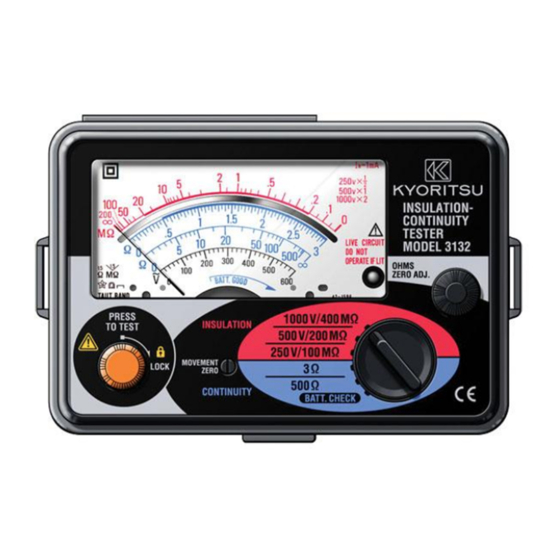
4. Instrument layout ①Meter movement zero adjust ②Test button ③Scale plate ④Input connector ⑤LIVE circuit lamp ⑥OHMS zero adjust ⑦Range selector switch ⑧Test probe (Red) LINE probe ⑨Test probe (Black) EIRTH probe ⑩Test probe cap (Red) ⑪Test probe cap (Black) ⑫Alligator clip (Black) ⑬Protective fingerguard —... - Page 12 Protective fingerguard Protective fingerguard: It is a part providing protection against electrical shock and ensuring the minimum required air and creepage distances. Cap: Uncapped condition for CAT II environment Capped condition for CAT III/ IV environments The Cap should be firmly attached to the probes. —...
-
Page 13: Preparation For Measurement
5. Preparation for measurement 5-1 Mechanical Zero Adjustment Check that the pointer lines up with the middle of the mark on the scale correctly. If not, adjust it by rotating the meter movement zero adjust with a screwdriver, etc. 5-2 Battery Voltage Check ①... -
Page 14: Measurement
6. Measurement 6-1 AC Voltage Warning Function # DANGER ● Never open the battery compartment cover when making measurement. ● Verify proper operation on a known source before use or taking action as a result indication of the instrument. ● Stop using the test lead if the outer jacket is damaged and the inner metal or color jacket is exposed. -
Page 15: Insulation Resistance Measurement
6-2 Insulation Resistance Measurement # DANGER ● Always test the circuit of equipment to ensure it is surely de-energized before measurement according to the instruction of 6-1. ● Never make measurement on a circuit in which earth potential of 600V or higher exist. - Page 16 ④ Check the circuit under test is not energized as follows. Connect the test probe to the circuit under test and read a voltage value. If the circuit is live, the meter indicates the voltage, the live circuit lamp is lit, and warning buzzer sounds.
-
Page 17: Continuity Testing (Resistance Tests)
● Output voltage characteristics The insulation resistance tester must be capable of maintaining the required test voltage when providing a steady atate current of 1mA. 0.5MΩ for the 500V test and 1MΩ for the 1000V test. ... - Page 18 # CAUTION ● Never press the test button if the live circuit warning lamp is lit or the warning buzzer sounds. This may damage the circuit. ● In case that an additional operating circuit connected in parallel to the circuit under measurement, the measurement error might be caused due to the effects of impedance of the circuit connected in parallel or transient current.
-
Page 19: Battery & Fuse Replacement
7. Battery & Fuse Replacement # DANGER ● Never open the battery compartment cover when making measurement. To avoid possible electrical shock, disconnect the test probe before opening the cover for battery and fuse replacement. 7-1 Battery Replacement ① Disconnect the test probe from the instrument. ②... -
Page 20: Notes On Accessories
8. Notes on Accessories 8-1 Case Lid The case can be fitted under the housing case as illustrated bellow. ① Open the case lid as shown. ② Turn it 180 degrees. ③ Put the case lid under ④ Hook it on housing case. ... -
Page 21: Cleaning Of The Instrument
9. Cleaning of the instrument ◎ Cleaning the meter cover This tester is managed by our company s quality standard and is delivered in the best condition after passed the inspection. But in the dry time of winter static electricity sometimes builds up on the meter cover due to the characteristic of plastic. -
Page 22: Service
10. Service If this tester should fall to operate correctly, return it to your nearest distributors starting the exact nature of the fault. Before returning the unit, make sure that: a) operating instructions have been followed b) Leads have been inspected c) Fuse has been checked d) Battery has been checked e) The unit is returned with all accessory leads... - Page 24 DISTRIBUTOR Kyoritsu reserves the rights to change specifications or designs described in this manual without notice and without obligations. 5-18 92-1493B...
Need help?
Do you have a question about the 3132A and is the answer not in the manual?
Questions and answers