
Related Manuals for Kyoritsu Electrical Instruments Works 4200


Summary of Contents for Kyoritsu Electrical Instruments Works 4200
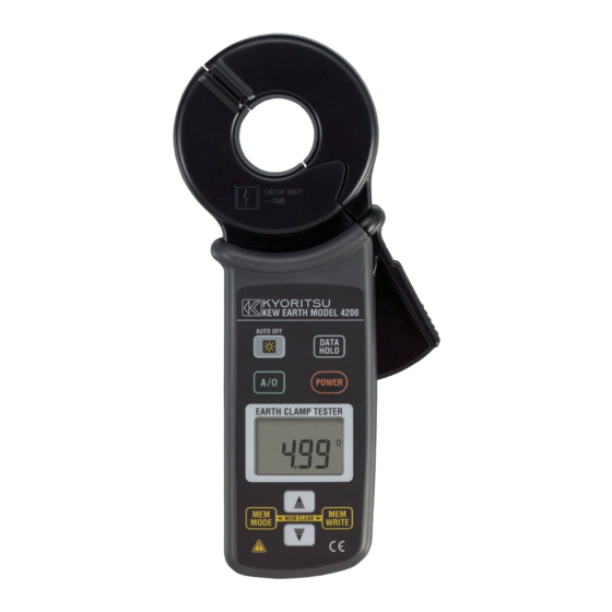
- Page 1 INSTRUCTION MANUAL DIGITAL EARTH CLAMP TESTER MODEL 4200 KYORITSU ELECTRICAL INSTRUMENTS WORKS, LTD.
-
Page 2: Table Of Contents
Contents 1. Safety warnings .................. 1 2. Features .................... 3 3. Specification .................. 4 4. Instrument layout ................... 6 5. Measurement principle ................ 7 6. Preparation for measurement .............. 9 7. Measuring method ................ 10 7-1 Normal measurement of current ............ 11 7-2 Measurement of Balance leakage current ........ 11 7-3 Measurement of earth resistance ........... 12 8. Other functions .................. 14 8-1 Auto power-off function .............. 14 8-2 Data hold function................ 14 8-3 Buzzer function ................ 14 8-4 Backlight function ................ 14 8-5 Memory function ................ 15 9. Battery replacement ................ 16 10. Service .................... 17... -
Page 3: Safety Warnings
1. Safety Warnings This instrument has been designed, manufactured and tested according to IEC 61010: Safety requirements for Electronic Measuring apparatus, and delivered in the best condition after passed the inspection. This instruction manual contains warnings and safety procedures which have to be observed to ensure safe operation of the instrument and maintain it in a safe condition. Thus, these operating instructions have to be read prior to using the instrument. WARNING ¡ Read through and understand the instructions contained in this manual before using the instrument. - Page 4 DANGER ¡ Never make measurement on a circuit in which the electrical potential exceeds AC300V. ¡ Do not make measurement when thunder is rumbling. Stop measurement and take off the instrument from the object under test. ¡ Do not attempt to make measurement in the presence of flammable gasses. Otherwise, the use of the instrument may cause sparking, which can lead to an explosion. ¡ To avoid electrical shock by touching the equipment under test or its surroundings, be sure to wear insulated protective gear. ¡ Transformer jaws are made of metal and their tips are not completely insulated. Be especially careful about the possible shorting where the equipment under test has exposed metal parts. ¡ Never attempt to use the instrument if its surface or your hand are wet. ¡...
-
Page 5: Features
2. Features This instrument is a digital clamp-on earth resistance tester, and it is used in multi- earthed systems. Can measure the earth resistance by simply clamping around the earthed wires. This instrument also equips AC current function to measure current up to 30A same to our traditional leakage clamp meters. ¡ Wide measuring range (Auto-ranging) Earth resistance Max. 1200Ω Min. resolution 0.01Ω AC current Max. 30A Min. resolution 0.1mA ¡ Noise check function A function to detect current, which effects on an earth resistance measurement and display the NOISE mark on the LCD. ¡... -
Page 6: Specification
3. Specification ¡ Measuring range and accuracy Function Range Resolution Measuring range Accuracy 20Ω 0.01Ω 0.00 〜 20.99Ω ±1.5%±0.05Ω 16.0〜99.9Ω ±2%±0.5Ω Earth resistance 200Ω 0.1Ω 100.0〜209.9Ω ±3%±2Ω (Auto-ranging) 160 〜 399Ω ±5%±5Ω 1Ω 400 〜 599Ω ±10%±10Ω 1200Ω 10Ω 600 〜 1260Ω − 100mA 0.1mA 0.0〜104.9mA ±2%±0.7mA AC current (ACA) 1000mA 80〜1049mA (sine wave) (50Hz/60Hz) - Page 7 ¡ Applicable standards IEC61010-1: 2001 (CAT. IV 300V Pollution degree2) IEC61010-2-032: 2002 IEC61326: 2000 (EMC standard) ¡ Electrostatic discharge Performance criteria B immunity ¡ Withstand voltage AC5320Vrms/ 5 seconds Between the Transformer jaws fitted parts and Case enclosure (except for jaws) ¡ Insulation resistance 50MΩ or more at 1000V Between the Transformer jaws fitted parts and Case enclosure (except for jaws) ¡ Conductor size Approx. 32mm in diameter max. ¡ Dimension 246(L) x 120(W) x 54(D)mm ¡ Weight Approx. 780g (including batteries) ¡ Accessories Battery R6P : 4pcs Instruction manual : 1pce Resistor for operation check : 1pce (MODEL8304) Hard case MODEL9128 : 1pce <Supplemental remarks>...
-
Page 8: Instrument Layout
4. Instrument layout ¡ Name of each parts and buttons 1 Transformer jaw 2 Trigger 3 Backlight button Switches on/off the backlight. 4 Function button Switches ACA/ Earth resistance function. 5 Memory mode button Check the measured value with each data number. 6 Data hold button Holds the indicated value. Release the held value. 7 Power button Turns on/off the instrument. 8 Display unit (LCD) 9 Cursor button (UP) Selects data number; to save the measured ... -
Page 9: Measurement Principle
5. Measurement principle This instrument can measure the earth resistance to earth in multi-earthed system. Let's regard earth resistance under test as Rx, and the other earth resistances as , R , …Rn. Of these earth resistances, R , R , …Rn can be considered that they are connected in parallel. And can be regarded as a combined resistance Rs. The Rs can be regarded small enough against Rx since a combined resistance consists of several resistances. Following is an equivalent circuit diagram of this circuit. ― 7 ―... - Page 10 By applying the Voltage (V) to the circuit from the Transformer jaw (CT1), current I is (shall be flowed) flowed corresponding to the earth resistance. R can be put out by the calculation after detecting the current with the other Transformer jaw (CT2). In this case, R displayed in this instrument can be regarded as Rx because Rs can be regarded small enough against Rx. C T 1 C T 2 CAUTION This instrument cannot support the measurement for the locations with following earth systems. ¡ Single-earth that is not connected to other earths. (Lightning rod, etc.) ¡...
-
Page 11: Preparation For Measurement
6. Preparation for measurement CAUTION This instrument performs self-calibration for about 3 seconds when it is turned on. (" " is displayed on the LCD.) Do not clamp on to any conductor or open the jaws in this period. Otherwise, inaccurate measurement may occur. (1) Check the battery voltage When nothing is displayed on the LCD, press the power button and turn on the instrument. Battery voltage is enough when indication is clear and the " " mark is not displayed on the LCD after turning on the instrument. Follow the procedure described in and replace 9. Battery replacement the batteries with new one when any of following symptoms is noted. Otherwise, accurate measurement and proper saving cannot be ensured. -
Page 12: Measuring Method
7. Measuring method DANGER ¡ Never make measurement on a circuit in which the electrical potential exceeds AC300V. ¡ Transformer jaws are made of metal and their tips are not completely insulated. Be especially careful about the possible shorting where the equipment under test has exposed metal parts. ¡ Never make measurement with the Battery cover removed. ¡... -
Page 13: Normal Measurement Of Current
7-1 Normal measurement of current * Press the Function button and select the ACA function. * Confirm the displayed unit is " mA ", and the " MEM " mark is not displayed at the upper left on the LCD. * Press the trigger to open the Transformer jaws, and close them over one conductor only. * Measured current value is displayed on the LCD. (Earth leakage current that flows through an earthed wire can be measured by this method.) 7-2 Measurement of Balance leakage current * Press the Function button and select the ACA function. * Confirm the displayed unit is " mA ", and the " MEM " mark is not displayed at the upper left on the LCD. * Clamp onto all conductors except an earthed wire. ... -
Page 14: Measurement Of Earth Resistance
7-3 Measurement of earth resistance CAUTION ¡ Follow the procedure described in "7-1 Normal measurement of current" and measure the current flowing on the earthed wire prior to the measurement of earth resistance. In case that the " " mark is displayed at the upper right of the LCD, it means that a great error would be included in the measured result. To avoid such inaccurate measurement, reduce the current flowing on the earthed wire by turning off the device from which current is applied to the earthed line under test. - Page 15 E a r t h r e s i s t a n c e m e a s u r e m e n t o f a p o l e e a r t h i n g e l e c t r o d e . E a r t h r e s i s t a n c e m e a s u r e m e n t o f a n e a r t h i n g e l e c t r o d e i n a s t r e e t l i g h t i n g s y s t e m .
-
Page 16: Other Functions
8. Other functions 8-1 Auto power-off function This is a function to prevent the instrument from being left turned on and conserve battery power. The instrument automatically turns off about 10 minutes after the last button operation. To return to the normal mode, press the Power button again and turns on the instrument. ◇ The buzzer sounds before the instrument turns off. ◇ To disable the auto power-off function, follow the procedure below. (1) Turn on the instrument by pressing the Power button with the Data hold button ... -
Page 17: Memory Function
8-5 Memory function This is a function to save and display the measurement results. ¡ Saving the measurement results (1) Any data number (between 1 and 100) can be selected with the Cursor button or at ACA or Earth resistance function, and save the measurement results. ◇ When the Cursor button is being pressed, the number switches quickly. (2) To save the measurement result being displayed on the LCD, press the Save button ... -
Page 18: Battery Replacement
9. Battery replacement WARNING ¡ In order to avoid possible shock hazard, take off the instrument from the conductor under test and turn off the instrument before trying to replace the batteries. CAUTION ¡ Do not mix new and old batteries. Never use the different kinds of batteries at the same time. ¡ Install batteries in the orientation as shown inside the battery compartment, observing correct polarity. When the battery voltage warning mark " " is displayed on the upper left of the LCD, replace the batteries. Note that the display blanks and " "... -
Page 19: Service
10. Service If the instrument should fail to operate correctly, return it to your local distributor from who you purchased this instrument stating the exact nature of the fault. For service, the resistor for operation check (MODEL8304) shall be attached and returned together with the instrument. Before returning the instrument, make sure that: a) Operating instructions have been followed b) Battery has been checked Remember, the more information written about the fault, the quicker it will be serviced. ― 17 ―...
Need help?
Do you have a question about the 4200 and is the answer not in the manual?
Questions and answers