Table of Contents
Advertisement
Quick Links
Right Angle Transfer Module
F-RAT-NX75
Flat-Right Angle Transfer
Read this manual before use
Thank you for purchasing the Right-Angle Transfer Module
(hereinafter referred to as "this product").
Make sure to read this manual carefully before using, and start
using only after you have understood all the product' s functions,
safety information and precautions.
After reading the manual, make sure to keep it safe in a specified
place for future use, whenever necessary.
ITOH
1
Module
No.516
Advertisement
Table of Contents

Subscribe to Our Youtube Channel
Related Manuals for ITOH DENKI POWER MOLLER PLUS F-RAT-NX75


Summary of Contents for ITOH DENKI POWER MOLLER PLUS F-RAT-NX75
- Page 1 Right Angle Transfer Module F-RAT-NX75 Flat-Right Angle Transfer Read this manual before use Thank you for purchasing the Right-Angle Transfer Module (hereinafter referred to as “this product”). Make sure to read this manual carefully before using, and start using only after you have understood all the product’ s functions, safety information and precautions.
- Page 2 Features F-RAT-NX75 User Manual Features Features of this product ・ This product is a module to divert at a right angle without changing its level, and there is no impact on the trays. ・ All-electric control. No pneumatics, which do not require compressor. Operation description (when diverting at a right angle)
-
Page 3: Introduction
1. Introduction Disclaimer This product is designed as a general industrial device. Do not use for other applications. We do not take any responsibility for any damage that may result from the disregarding of these warnings. Also, in the event that an accident results from the use of this product, we do not compensate for any damage, including abnormalities of equipment, connection devices, and/or software, any damage resulting from malfunctions, and/or any other secondary damage. -
Page 4: Procedures From Installation To Operation
Procedures from installation to operation F-RAT-NX75 User Manual Procedures from installation to operation Read this manual Start using only after you have understood all the product’ s functions, safety information, and precautions. Advance preparation P.14 ~ Prepare the 24V DC power supply, such as DC power supply units. Prepare control devices, such as PLCs. -
Page 5: Table Of Contents
INDEX F-RAT-NX75 User Manual INDEX … 2 Introduction … 4 Procedures from installation to operation … 6 Safety precautions 3-1. General precautions … 8 3-2. Precautions on installation … 10 … 11 3-3. Precautions on wiring 3-4. Precautions related to control …... -
Page 6: Safety Precautions
3. Safety precautions F-RAT-NX75 User Manual 3. Safety precautions For parts names in sentences, refer to 6. Structures (P.21). …… 8 3-1. General precautions …… 10 3-2. Precautions on installation …… 11 3-3. Precautions on wiring …… 11 3-4. Precautions related to control ……... - Page 7 Danger level F-RAT-NX75 User Manual 3. Safety precautions Danger level To prevent hazards to users and/or others, and/or damage to property in advance, the important precautions to be followed securely is described below. ■ The degree of hazard and/or damage that may result if a user disregards the description and operates the product improperly is categorized by the following symbols and explained below.
-
Page 8: General Precautions
General precautions F-RAT-NX75 User Manual 3. Safety precautions 3-1. WARNING General precautions Do not use the product near places subject to explosive, flammable gas, and/or corrosive atmosphere, and/or combustible materials. Failure to follow this could result in explosion, fire, electric shock and/or injury. - Page 9 General precautions F-RAT-NX75 User Manual 3. Safety precautions 3-1. CAUTION General precautions Stop operation when abnormal sound is heard during operation. Failure to follow this could result in unexpected accidents. Do not use in a way exceeding the range of the product specifications.
-
Page 10: Precautions On Installation
Precautions on installation F-RAT-NX75 User Manual 3. Safety precautions 3-1. CAUTION General precautions Do not turn on the power when trays are unstable. Failure to follow this could result in injury, accidents, and/or damage due to load collapse. Make sure to perform the start-up inspection, and check that devices are free from any abnormalities, and that safety equipment functions correctly before using the product. -
Page 11: Precautions On Wiring
Precautions on wiring F-RAT-NX75 User Manual 3. Safety precautions 3-2. CAUTION Precautions on installation Take appropriate measures to prevent trays from popping out of the equipment. For example, mount guide rails on the conveyor frames. Failure to follow this could result in workers getting injured by trays popping out of the equipment. -
Page 12: Precautions Related To Operation
Precautions related to operation F-RAT-NX75 User Manual 3. Safety precautions 3-5. CAUTION Precautions related to operation Do not forcibly move trays when they are placed on the carrier wheels. Failure to follow this could result in damage and/or malfunction. Make sure to perform the start-up inspection before starting operation. - Page 13 · Check that all parts are installed. Failure to follow this could result in malfunction and/or unexpected accidents. Make sure to prepare repair/replacement parts designated by ITOH DENKI. Using parts other than those designated by ITOH DENKI could result in malfunction.
-
Page 14: Advance Preparation
preparation 4. Advance F-RAT-NX75 User Manual 4. Advance preparation... - Page 15 Emergency stop equipment F-RAT-NX75 User Manual 4. Advance preparation Wiring image 【 Important 】 As for the sensor input, and input/output signals of driver cards, adopt the number of inputs/outputs based on operation.
- Page 16 Emergency stop equipment F-RAT-NX75 User Manual 4. Advance preparation Items to be prepared Before introducing this product, prepare the following devices separately. by customers This product does not include the emergency stop equipment. Emergency stop Customers must make sure to install it. equipment Install the emergency stop equipment on the side of the DC power supply unit to which the power is supplied.
- Page 17 24V DC power supply F-RAT-NX75 User Manual 4. Advance preparation 24V DC power supply Power supply equipment to supply 24V DC to this product ● Switching power supply (24V DC/10A, 240W or more) ● Rectified power (With a rectifying capacitor, ripple rate 10% or below) ●...
- Page 18 MDR extension cable (option) F-RAT-NX75 User Manual 4. Advance preparation Wiring materials Necessary for wiring of power and signal cables, branch connectors, driver cards, controllers, such as sensors or PLCs, and power supply. 〈Available wire diameter for driver card connectors〉 Driver card CBK-109 CB-016...
-
Page 19: Product Check
Product check F-RAT-NX75 User Manual 5. Product check... - Page 20 Checking the model F-RAT-NX75 User Manual 5. Product check Checking the model Unpack the product, and check that the product model is as ordered. Model ①Check that the main unit is free from any abnormalities, such as traces of scratches, Checking appearance dents, dirt, and/or corrosion (rust).
- Page 21 Checking accessories F-RAT-NX75 User Manual 5. Product check Checking accessories Check that all the following items are ordered. Driver cards Depending on the F-RAT input and output signal type, driver cards with the NPN (N) or PNP (P) signal input are available. For F-RAT-NX75 WITH CB SERIES CARDS CARDSRAWWIHTWITHWIIBnPNnpnnNPNNPn{nS ESERIESERIESCAR...
-
Page 22: Structures
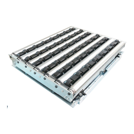
Structures F-RAT-NX75 User Manual 6. Structures... - Page 23 Product designation F-RAT-NX75 User Manual 6. Structures Structures Carrier wheel transfer MDR(M1) Roller transfer MDR(M2) Drive switching MDR(M3) φ 48.6 Idler(φ48.6) Carrier wheel Idler(φ38) Carrier wheel cassette Product label Product label *The photo is fo *The photo is for size 7550. Product designation Product label Model...
-
Page 24: Installation/Wiring
Installation/Wiring F-RAT-NX75 User Manual 7. Installation/Wiring …… 25 7-1. Before installation …… 35 7-2. Installation …… 36 7-3. Wiring... -
Page 25: Before Installation
Size 6040・6050 F-RAT-NX75 User Manual 7. Installation/Wiring ・Prepare stands, and perform frame processing in advance by reference to the mounting 7-1. holes in dimensions. Before installation ・Determine the mounting location for zone sensors to check the existence of trays, and area sensors to check loading and discharging. - Page 26 Size 6060・6070 F-RAT-NX75 User Manual 7. Installation/Wiring Size 6060 L595mm×W595mm (Mounting nut position) * Cable * Carrier wheel transfer Roller transfer Size 6070 L595mm×W695mm (Mounting nut position) * Cable 4×取り付け用ナット(M8) * Carrier wheel transfer 1000 Roller transfer...
- Page 27 Size 6080・7540 F-RAT-NX75 User Manual 7. Installation/Wiring Size 6080 (Mounting nut position) L595mm×W795mm 22.5 22.5 * Cable (Pipe size) 4 × Mounting nut(M8) *Guide for cable marginal projecting length (mm) Size 7540 L745mm×W395mm (Mounting nut position) * Cable *...
- Page 28 Size 7550・7560 F-RAT-NX75 User Manual 7. Installation/Wiring Size 7550 L745mm×W495mm (Mounting nut position) * Cable * Carrier wheel transfer Roller transfer 1000 Size 7560 L745mm×W595mm (Mounting nut position) * Cable *...
- Page 29 Size 7570・7580 F-RAT-NX75 User Manual 7. Installation/Wiring Size 7570 (Mounting nut position) L745mm×W695mm * Cable * Carrier wheel transfer Roller transfer Drive switching Size 7580 (Mounting nut position) L745mm×W795mm * Cable * Carrier wheel transfer Roller transfer...
- Page 30 Size 9040・9050 F-RAT-NX75 User Manual 7. Installation/Wiring Size 9040 (Mounting nut position) L895mm×W395mm * Cable * Carrier wheel transfer Roller transfer 1100 Size 9050 L895mm×W495mm (Mounting nut position) * Cable *...
- Page 31 Size 9060・9070 F-RAT-NX75 User Manual 7. Installation/Wiring Size 9060 L895mm×W595mm (Mounting nut position) * Cable * Carrier wheel transfer Roller transfer Size 9070 L895mm×W695mm (Mounting nut position) * Cable * Carrier wheel transfer Roller transfer...
- Page 32 Size 9080 F-RAT-NX75 User Manual 7. Installation/Wiring Size 9080 (Mounting nut position) L895mm×W795mm * Cable *...
- Page 33 Mounting preparation for driver cards F-RAT-NX75 User Manual 7. Installation/Wiring Hole processing on frames and control panel Mounting preparation for driver cards ・Perform mounting processing on the frames and control panel by reference to the mounting holes for driver cards. ・For cable opening and projection from the F-RAT main unit, refer to Mounting preparation for the F-RAT main unit (P.24).
- Page 34 Mounting preparation for driver cards F-RAT-NX75 User Manual 7. Installation/Wiring Preparation of MDR If the mounting location of the F-RAT main unit is far from that of driver cards, prepare the MDR extension cables separately. extension cables For CBK-109 or IB-E04(12P extension cable) :M-F-EXT-12PIN-(600/1200) ●...
-
Page 35: Installation
Installing the F-RAT main unit F-RAT-NX75 User Manual 7. Installation/Wiring 7-2. Necessary tools Installation 13mm Phillips head screwdriver Precision slotted (No.2) ratchet wrench screwdriver Stripper Installing the F-RAT main unit Installing the F-RAT main unit Carry this product to the installing location. ■... -
Page 36: Wiring
Wiring F-RAT-NX75 User Manual 7. Installation/Wiring Mounting driver cards Mounting driver cards Use the included screws and nuts to mount driver cards on the conveyor frames or control panel. ■ Recommended tightening torque: 1.5 to 1.9N·m 1.5~1.9N・m Mounting sensors, control devices, and power supply units Mounting sensors, control devices, and Mount customer-prepared zone sensor and area sensor for loading and discharging,... - Page 37 Wiring for CBK-109 F-RAT-NX75 User Manual 7. Installation/Wiring...
- Page 38 Wiring for CBK-109 F-RAT-NX75 User Manual 7. Installation/Wiring Wiring for CBK-109 〔CBK-109〕 CBK-109 M1:For carrier wheel transfer CBK-109FN:0V 0-10V IN V-IN CBK-109FN:0V CBK-109FP:24V ■ Connector descriptions DC24V (Power) DC 24V Functions Detailed descriptions ・Outputs 2-pulse signal per rotation of the internal motor. ・NPN open collector output.
- Page 39 Wiring for CB-016 F-RAT-NX75 User Manual 7. Installation/Wiring 〔CB-016〕 Wiring for CB-016 M2:For roller transfer CB-016 CB-016BN6:0V 0-10V IN CB-016BN6:0V CB-016BP6:24V DC24V ■ Connector descriptions (Power) DC24V Functions Detailed descriptions ・Outputs 2-pulse signal per rotation of the internal motor. ・NPN open collector output. Motor pulse #5 Output ・Attach protection resistance so that the output is 25 mA or less.
- Page 40 Setting driver cards F-RAT-NX75 User Manual 7. Installation/Wiring Settings for M1: CBK-109/M2 and M3: CB-016 Setting driver cards Turn the driver card volume to the following (factory setting). Minimum ■ The carrier wheel speed for this product of the nominal speed of 17 m/min type is 61.5 m/min (factory setting).
-
Page 41: Control/Operation
8. Control/Operation F-RAT-NX75 User Manual 8. Control/Operation …… 42 8-1. Basic operation …… 43 8-2. Switching the transfer direction …… 44 8-3. Changing the speed …….. 46 8-4. What to do before operation …….. 47 8-5. Timing Chart Example... -
Page 42: Basic Operation
Device configuration image F-RAT-NX75 User Manual 8. Control/Operation Device configuration This product image F-RAT main unit Driver cards :CBK-109 CN2#1 Carrier wheel RUN signal transfer MDR :CB-016 CN2#1 Roller transfer MDR RUN signal :CB-016 CN2 #1, 2 Drive switching MDR Switch signal Proximity Sensor Area sensor for loading... -
Page 43: Switching The Transfer Direction
Switching the transfer direction F-RAT-NX75 User Manual 8. Control/Operation 8-2. Switching the transfer direction Switching the The transfer direction can be set by DIP-SW on the driver card, and signal input. transfer direction ■ When changing the direction, check the F-RAT main unit installation direction. 〔M1:CBK-109 / M2:CB-016〕... -
Page 44: Changing The Speed
Changing the transfer speed F-RAT-NX75 User Manual 8. Control/Operation 8-3. Changing the transfer speed Changing the There are two types of settings to change speed: the internal speed setting to change transfer speed the speed by switches on the driver card, and the external speed setting to change the 〔M1:CBK-109 / M2:CB-016〕... - Page 45 Changing the speed F-RAT-NX75 User Manual 8. Control/Operation 8-3. Changing the speed 〔M1:CBK-109 / M2:CB-016〕 [M1:Carrier wheel speed] Speed chart Speed accuracy: ±3% (m/min) SW1#5:ON SW1#5:OFF 61.5 56.4 53.9 51.3 48.7 46.2 41.1 38.4 35.9 33.4 30.8 28.2 25.6 23.1 20.5 18.0 15.5 12.8 10.3 7.7 59.8 56.4 53.9 51.3 48.7 46.2 41.1 38.4 35.9 33.4 30.8 28.2 25.6 23.1 20.5 18.0 15.5 12.8 10.3 7.7 External voltage 4.1 3.6...
-
Page 46: What To Do Before Operation
Start-up inspection F-RAT-NX75 User Manual 8. Control/Operation 8-4. To prevent accidents and/or damage to devices during operation, refer to the below What to do before operation, and check the safety. before operation Items to check before turning on the power Start-up inspection Turn off the power of all connected devices, and perform the following inspection, taking necessary measures. -
Page 47: Timing Chart Example
Start-up inspection F-RAT-NX75 User Manual 8. Control/Operation Timing Chart Example... - Page 48 Trial run F-RAT-NX75 User Manual 8. Control/Operation Trial run Items to check before the trial run Check below before the trial run. ・When the roller transfer MDR and/or idlers have been replaced, check that the drive belts have been mounted in the correct groove positions. ・Check all parts are installed.
-
Page 49: Maintenance/Inspection
9. Maintenance/Inspection F-RAT-NX75 User Manual 9. Maintenance/Inspection …… 50 9-1. Driver card LED display and error countermeasures …… 52 9-2. Before replacement work …… 54 9-3. Replacement of MDR for roller transfer/idlers/roller drive belts …… 59 9-4. Replacement of the carrier wheel cassette... -
Page 50: Driver Card Led Display And Errors Countermeasures
〔CBK-109〕Error details F-RAT-NX75 User Manual 9-1. If errors occur with this product, identify the cause of errors, and perform recovery work. Driver card LED display and error countermeasures Checking the Identify the cause of errors by checking LEDs and error signal output on driver cards, driver card status and restore the product. - Page 51 〔CBK-109〕Error details F-RAT-NX75 User Manual 〔CB-016〕 For roller transfer LED display explanation Errors can be checked by PWR (Green), ERR (Red), and signals from CN2#4. ■ When error signals have been released by CN2#1 (RUN / STOP), the F-RAT instantly starts up when RUN is input.
-
Page 52: Before Replacement Work
Replacement parts F-RAT-NX75 User Manual Maintenance/Inspection If any abnormalities, such as damaged parts, are found, immediately take actions, including replacement with new part Before replacement Product label ・Check the model of this product, and prepare parts to be replaced Model with in advance. - Page 53 Replacement parts F-RAT-NX75 User Manual 9. Maintenance/Inspection Roller drive belt Part number:2PJ-265 (V-ribbed belt) The part number of which only belts, size □□60 *1 type, are used to link Φ38 idlers, is 2PJ-246. *1Indicates size (W direction) for the model of this product Example) F-RAT-NX75-F60-7560-CN Roller transfer MDR *1...
-
Page 54: Replacement Of Mdr For Roller Transfer/Idlers/Drive Belts
Replacement of roller transfer MDR/idlers F-RAT-NX75 User Manual 9. Maintenance/Inspection 9-3. If any abnormalities are found in one of the roller transfer MDR, idlers, and/or Replacement of roller drive belts, replace them according to the following methods. roller transfer MDR/idlers /roller drive belts Before replacement Before replacement, prepare necessary tools. - Page 55 Replacement of roller transfer MDR/idlers F-RAT-NX75 User Manual 9. Maintenance/Inspection Replacement procedures Slide the spring-loaded shaft from the fixed hole(①), and remove the idler from the frame(②) <Figure seen from the side> Frame Fixed hole ①Push the spring-loaded shaft ②Remove it from until it has passed through the the frame fixed hole...
- Page 56 Replacement of roller transfer MDR/idlers F-RAT-NX75 User Manual 9. Maintenance/Inspection Replacement procedures Lift up the tip of the roller transfer MDR(①), and remove the roller drive belt.(②)Remove the roller transfer MDR(③), and pull the power cable off the fixed hole on the frame(④)...
- Page 57 Replacement of roller transfer MDR/idlers F-RAT-NX75 User Manual 9. Maintenance/Inspection Replacement procedures Mount the roller drive belt on the V-ribbed pulley of the roller transfer MDR(①), align the tip of the attaching shaft with the ①Mount the roller notch shape, and fit it into the drive belt frame(②)...
- Page 58 Replacement of roller transfer MDR/idlers F-RAT-NX75 User Manual 9. Maintenance/Inspection Align the tip of the attaching shaft Replacement procedures on the side of the belt on the V-ribbed pulley, where the roller drive belt has been mounted, with the notch shape on the frame, Attaching shaft and fit it into the frame ■...
-
Page 59: Replacement Of The Carrier Wheel Cassette
Replacement of the carrier wheel cassette F-RAT-NX75 User Manual 9. Maintenance/Inspection 9-4. If any abnormalities are found in the carrier wheels, replace the whole carrier wheel cassette. Replacement of the carrier wheel cassette Before replacement Before replacement, prepare necessary tools. Tools to be used 8 mm/19 mm wrench 5 mm hex. - Page 60 Replacement of the carrier wheel cassette F-RAT-NX75 User Manual 9. Maintenance/Inspection Replacement procedures Mounting the carrier wheel cassette on the F-RAT main unit On the side of Check the model of the removed V-ribbed pulley carrier wheel cassette and replacement carrier wheel cassette. Location of the Wheel for Indication example)
-
Page 61: Troubleshooting
Troubleshooting F-RAT-NX75 User Manual 10. Troubleshooting... - Page 62 F-RAT does not operate F-RAT-NX75 User Manual 10. Troubleshooting If you believe the product may be malfunctioning, check the contents described in this section before contacting the supplier and/or asking for repair. Symptoms F-RAT does not operate Items to be checked Countermeasures References 7.
- Page 63 F-RAT-NX75 User Manual 10. Troubleshooting Symptoms When loading, Items to be checked Countermeasures References trays get stuck, or 7. Installation/ Is the load conveyor level the Align levels of the load conveyor cannot be transferred Wiring same as the level of the F-RAT? and the F-RAT.
- Page 64 F-RAT-NX75 User Manual 10. Troubleshooting Symptoms ・The speed cannot be Items to be checked Countermeasures References changed ・The speed setting is To change the carrier wheel To change the carrier wheel Changing the transfer speed speed, have you operated the speed, operate the switch on incorrect (⇒P.47)...
-
Page 65: Appendix
Appendix F-RAT-NX75 User Manual Appendix... -
Page 66: Appendix 1. Product Specifications
F-RAT main unit specifications F-RAT-NX75 User Manual Appendix 1. Product specifications F-RAT main unit specifications Size 60□□ 6040 6050 6060 6070 6080 Total length (L) Carrier wheel transfer direction 595mm F-RAT Total width (W) Roller transfer direction 395mm 495mm 595mm 695mm 795mm main unit... - Page 67 Driver card specifications F-RAT-NX75 User Manual Appendix 1. Product specifications For roller transfer and Driver card Specifications For carrier wheel transfer lift/lower CBK-109F□ CB-016B□7 Model (□=N: NPN, P: PNP) Power supply voltage 24 Volt DC ± 5% Rated Voltage 24V DC Static Current 0.06 A 0.03 A...
- Page 68 Driver card specifications F-RAT-NX75 User Manual Transfer throughput 6000 ・F-RAT-NX75, nominal speed of 60 m/min, size 6050 type ・Using area sensors ・Ambient temperature:20℃ 5000 ・Conditions of trays: Cardboard of L 405 mm × W 35030 kg ・Depends on the diverting conditions from the status where trays remain in each load C/V zone 4000 3000...
-
Page 69: Appendix 2. Replacement Parts / Options
Replacement parts/Options F-RAT-NX75 User Manual Appendix Appendix 2. ■ Do not store carrier wheel cassettes in places subject to high temperature, high humid- ity, and/or direct sunlight. Failure to follow this could result in its lifetime to be signifi- Replacement parts/Options cantly shortened. -
Page 70: Appendix 3. Residual Risk List
Residual risk F-RAT-NX75 User Manual Appendix 【Seriousness of harm】 Appendix 3. WARNING: Indicates that there is a possibility that severe injury or even death may result if protective measures have Residual risk list/MAP not been taken CAUTION: Indicates that there is a possibility that minor injury may result if protective measures have not been taken Residual risk list Qualifications/ Measures that... - Page 71 Phone: +81 ( 0 ) 790 47 1225 Fax: +81 ( 0 ) 790 47 1328 www.itohden ki.co.jp ■ Europe, Middle East, Africa: Itoh Denki Europe SAS Phone: +33 ( 0 ) 4 50 03 09 99 Fax: +33 ( 0 ) 4 50 03 07 60 www.itoh-denki.com...
Need help?
Do you have a question about the POWER MOLLER PLUS F-RAT-NX75 and is the answer not in the manual?
Questions and answers