Table of Contents
Advertisement
Quick Links
Slide Open Gate Module
SOG
Slide Open Gate Module
〈 User Manual 〉
Read this manual before use
Thank you for purchasing the Slide Open Gate Module (hereinafter
referred to as "this product").
※This product refers to all products including standard accessories.
Customers are responsible for preparing the control equipment, carrying
out wiring, and making programs for operation.
This document includes basic descriptions about operation methods, lamp indications,
and various types of operations, assuming that customers have prepared the control
equipment, and finished wiring and making the control programs by referring to this
document. At the time of operation, be sure to prepare the control equipment, carry out
wiring, and have made the control programs according to your operation.
Make sure to read this manual carefully before using, and start
using only after you have understood all the product' s functions,
safety information and precautions.
After reading the manual, make sure to keep it safe in a specified
place for future use, whenever necessary.
ITOH DENKI
ITOH DENKI
ITOH DENKI
Carry
Module
No.607
Advertisement
Table of Contents

Related Manuals for ITOH DENKI POWER MOLLER PLUS SOG


Summary of Contents for ITOH DENKI POWER MOLLER PLUS SOG
- Page 1 At the time of operation, be sure to prepare the control equipment, carry out wiring, and have made the control programs according to your operation. ITOH DENKI ITOH DENKI ITOH DENKI Module No.607...
-
Page 2: Introduction
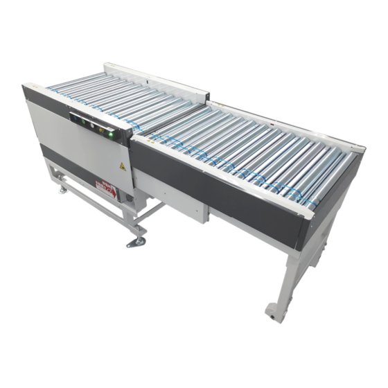
SOG User Manual 1. Introduction This product is material handling equipment that secures workers’ moving lines in a Features conveyor line. Pressing a button can open/close the gate to cut across a conveyor line. This product is composed of the base section and gate section conveyors, or can set up an opening of almost the same size as the base section conveyor. - Page 3 Caution : Installation, operation and usage of ITOH DENKI MDRs in combination ● with a control card designed by a third party could result in fatal phenomena such as fire, electric shock, injuries etc which are out of the responsibility of ITOH DENKI.
- Page 4 SOG User Manual 2. Procedures from installation to operation Procedures from installation to operation Read this manual Start using only after you have understood all the product´s functions, safety information, and precautions. Advance preparation Prepare the 24V DC power supply, such as P.13 〜 DC power supply units. Product check Open the package, and check the model, specifications, P.18 〜...
-
Page 5: Table Of Contents
SOG User Manual 2. Procedures from installation to operation INDEX Introduction …… 2 Procedures from installation to operation …… 4 Safety precautions …… 6 Advance preparation …… 13 Product check …… 17 Structures …… 19 Installation / Wiring …… 21 7-1. Before installation …… 22 7-2. External dimensions …… 23 7-3. Installation …… 26 7-4. Wiring …… 28 7-5. Setting driver cards …… 32 Control …… 34 8-1. I/O settings …… 35 8-2. Teaching (initial) settings …… 35 8-3. Operation in the gate section …… 36 8-4. Collision detection function …… 37 8-5. Entrapment detection function …… 37 8-6. Operation examples …… 38 ... -
Page 6: Safety Precautions
SOG User Manual 3. Safety precautions For parts names in sentences, refer to 6. Structures (P.19). - Page 7 SOG User Manual 3. Safety precautions To prevent hazards to users and/or others, and/or damage to property in advance, the Danger level important precautions to be followed securely are described below. ■ The degree of hazard and/or damage that may result if a user disregards the description and operates the product improperly is categorized as the following symbols and explained below.
- Page 8 SOG User Manual 3. Safety precautions 3-1. WARNING General precautions Do not use the product near places subject to explosive, flammable gas, and/or corrosive atmosphere, and/or combustible materials. Failure to follow this could result in explosion, fire, electric shock and/or injury. When using the product in places where serious accidents and/or damage may possibly occur, install backup and/or fail-safe functions systematically.
- Page 9 SOG User Manual 3. Safety precautions 3-1. CAUTION General precautions Do not turn on/off relays and/or contactors near power cables, signal cables, and/or driver cards. Failure to follow this could result in malfunction due to noise generation. LED or Pull-up/Pull-down circuits implemented in the output circuit of control devices could result in unexpected operation.
- Page 10 SOG User Manual 3. Safety precautions 3-2. WARNING Precautions on installation When hoisting this product, never enter the area under the suspended load. When hoisting, use appropriate hoisting equipment, and pay special attention to prevent the balance of the suspended load from being lost and/or falling. Also, have only qualified workers conduct the operation.
- Page 11 SOG User Manual 3. Safety precautions 3-3. CAUTION Precautions on wiring Turn off the power before carrying out wiring work on the terminal blocks. Failure to follow this could result in electric shock, malfunction, and/or accidents due to unexpected operation. Perform wiring so that cables securely come into contact with the terminal blocks.
- Page 12 Failure to follow this could result in malfunction and/or unexpected accidents. Make sure to prepare maintenance parts designated by ITOH DENKI. Using parts other than those designated by us could result in malfunction. Perform maintenance and inspection in a “Pollution Degree 2”...
-
Page 13: Advance Preparation
SOG User Manual 4. Advance preparation... - Page 14 SOG User Manual 4. Advance preparation Reference of wiring AC power supply PLC, etc. Breaker 24V DC power unit Grounding Safety circuit Breaker ■ As for the sensor input, and input/output signals of controllers, adopt the number of inputs/outputs based on customers’ operation. (Details ⇒ P.28) ■...
- Page 15 SOG User Manual 4. Advance preparation Devices to control this product, such as PLCs ② Control devices Necessary for wiring of power and signal cables to the terminal blocks. ③ Wiring materials terminal block 1 Compatible crimp terminals 1.25ー3/2ー3 terminal block 2/ Wire diameter: 0.08 to 1.5 mm2 (AWG: 28 to 16) terminal block 3 Flexible twisted wires ■...
- Page 16 SOG User Manual 4. Advance preparation ⑥ About the wiring method When overcurrent protection devices need to be installed to the 24V DC power supply unit, ⑥-1 When overcurrent some power supplies that need to conform to the safety standards (UL60950-1, etc.) require protection devices installation of the specified overcurrent protection device based on their specifications. In are required such cases, make sure to install the specified overcurrent protection device as described in the figure below.
-
Page 17: Product Check
SOG User Manual 5. Product check... - Page 18 SOG User Manual 5. Product check Checking the model After unpack, check that the product model is what you ordered. 〈 Product label details 〉 SLIDE OPEN GATE MODULE Model SOG2 − F60 − W050 − H070 − RG − CN RATED INPUT:DC24V, A PAYLOAD:max kg SERIAL No. ITOH DENKI CO.,LTD MADE IN JAPAN ① Check that the main unit is free from any abnormalities, such as traces of scratches, Checking appearance dents, dirt, and/or corrosion (rust).
-
Page 19: Structures
SOG User Manual 6. Structures... - Page 20 SOG User Manual 6. Structures Structures Product label Controller (on the other side) (on the other side) Base section zone sensor MDR for base section Operation BOX conveyor MDR for gate section conveyor Gate section zone sensor Base section Slide MDR (for opening/closing the gate) Gate section Manual unlocking device Operation BOX MODE ERROR STATUS Auxiliary wheel Illuminated SW SW SW Lamp Lamp (Blue) (Green) (White) (Yellow) (Green) ※ This layout is viewed from the drive belt side. The layout is opposite when viewed from the controller side. For how to operate, refer to 9. Operation. Product designation Product label SLIDE OPEN GATE MODULE Model SOG2 ...
-
Page 21: Installation/Wiring
SOG User Manual 7. Installation/Wiring 7-1. Before installation …… 22 7-2. External dimensions …… 23 7-3. Installation …… 26 7-4. Wiring …… 28 7-5. Setting driver cards …… 32... -
Page 22: Before Installation
SOG User Manual 7. Installation/Wiring 7-1. Before installation ■ Install this product in places with a mounting surface tilt (inclination) of 1/1000 or Installation environment less. ■ Install in locations where the weight of this product and totes can be sufficiently supported. (For the main unit weight, refer to P46) ■... -
Page 23: External Dimensions
SOG User Manual 7. Installation/Wiring 7-2. External dimensions 805 ( Pitch for anchor fixing) 4-∅14 ( Hole for anchor fixing) Transfer surface height:H060 S T A T U S E R R O R M O D E Transfer width Unit [mm] Model:W□ BF Length : W Outside frame dimension : W1 Outside cover dimension : W2 Pitch for anchor fixing:W3 1017 STATUS ERROR MODE... - Page 24 SOG User Manual 7. Installation/Wiring 805 ( Pitch for anchor fixing) 4-∅14 ( Hole for anchor fixing) Transfer surface height:H080 S T A T U S E R R O R M O D E Transfer width Unit [mm] Model:W□ BF Length : W Outside frame dimension : W1 Outside cover dimension : W2 Pitch for anchor fixing:W3 1017 STATUS ERROR MODE (Outside cover dimension)...
- Page 25 SOG User Manual 7. Installation/Wiring 805 ( Pitch for anchor fixing) 4-∅14 ( Hole for anchor fixing) Transfer surface height:H100 S T A T U S E R R O R M O D E Transfer width Unit [mm] Model:W□ BF Length : W Outside frame dimension : W1 Outside cover dimension : W2 Pitch for anchor fixing:W3 1017 STATUS ERROR MODE (Outside cover dimension)...
-
Page 26: Installation
SOG User Manual 7. Installation/Wiring 7-3. Installation Installation Necessary tools 13mm 13mm Phillips head screwdriver 24mm wrench Hammer closed wrench T-BOX wrench (No.2) Carry this product to the installing location. Level adjustment After fixing the product, adjust Level adjusting nut in the base section the level of conveyors adjacent 24mm ... - Page 27 SOG User Manual 7. Installation/Wiring ①Loosen the M8×10 hexagonal Cross section of the auxiliary wheel section Level adjustment bolts with a 13 mm closed in the gate section wrench and 13 mm T-BOX ② Hexagonal bolt wrench. M8×20 ②Use a 13 mm closed wrench ① ③ Hexagonal bolt to adjust the level by turning ...
-
Page 28: Wiring
SOG User Manual 7. Installation/Wiring 7-4. Wiring Wiring Remove the controller cover. Controller cover CB-016B□6 5.PLS HBS-202FN SPEED 4.ERR EROUT 3.V-IN 0-10V 2.DIR TB1 TB2 TB3 TB4 TB5 TB6 1.RUN SPEED P2401 P2401 CB-016BN6 5.PLS SPEED 4.ERR EROUT 3.V-IN 0-10V 2.DIR 1.RUN N2401 N2401 Driver card for MD1: ... - Page 29 SOG User Manual 7. Installation/Wiring Wiring on the terminal block 2 SW (White) (BS1) (Input and output for the SW (White) (BS3) operation BOX) SW (Green) (BS2) SW (Green) (BS4) Lamp (Yellow) (LMP4) Lighted SW (Blue) (SS1) Lamp (Yellow) (LMP2) Lighted SW (Blue) (SS2) Lamp (Green) (LMP3) Lighted SW (Blue) (SS1) Lamp (Green) (LMP1) Lighted SW (Blue) (SS2) TB1 TB2 TB3 TB4 TB5 TB6 To PLC ■ Terminal block 2 has the four-wire system. ■...
- Page 30 SOG User Manual 7. Installation/Wiring Control terminals of driver cards for MD1: Base section conveyor MDR and MD2: Gate section conveyor MDR Functions Detailed descriptions Unused Output Motor pulse output ・Open collector output. Output Error signal output ・Attach protection resistance so that the output is 25mA or less. Analog MDR external speed (Control) Unused input setting MDR rotation direction Up to 3mA Input switching...
- Page 31 SOG User Manual 7. Installation/Wiring Wiring from the terminal block 1 to the DC power supply unit DC24V P2401 P2401 N2401 N2401 ■ Compatible crimp terminals : 1.25ー3/2ー3 Connect a ground wire to the following position. Grounding terminal Screw size ※The same position on the controller side can also be used. Wiring example from the Output Input terminal blocks 2 and 3 to PLC Lamp (Green) SW (White) ...
-
Page 32: Setting Driver Cards
SOG User Manual 7. Installation/Wiring 7-5. Setting driver cards Perform driver card settings for MD1: Base section conveyor MDR and MD2: Gate Settings for MD1 and MD2 section conveyor MDR. CB-016B□6 5.PLS SPEED 4.ERR 3.V-IN 2.DIR 1.RUN ※1 ※2 ※2 OFF OFF Minimum Minimum SW1#3 is used for setting the rotation direction. ■... - Page 33 SOG User Manual 7. Installation/Wiring Transfer setting example ① Transfer setting example ② Transfer direction Transfer direction MD1: MDR for MD2: MDR for MD1: MDR for MD2: MDR for base section conveyor gate section conveyor base section conveyor gate section conveyor Rotation Rotation direction direction SW1#3 SW1#3 CN2#2 CN2#2 CN#1 CN#1 ※2 is used for setting the speed.
-
Page 34: Control
SOG User Manual 8. Control 8-1. I/O settings …… 35 8-2. Teaching (initial) settings …… 35 8-3. Operation in the gate section …… 36 8-4. Collision detection function …… 37 8-5. Entrapment detection function …… 37 8-6. Operation examples …… 38... -
Page 35: I/O Settings
SOG User Manual 8. Control 8-1. I/O settings Terminal block 2 Terminal block 1 Terminal block 3 Description Operation BOX PLC output LMP1/LMP3 Lamp (Green) Power/Operation indication STATUS PLC output LMP2/LMP4 Lamp (Yellow) Error indication ERROR PLC input BS1/BS3 SW (White) Conveyor close SW ← (→) ※ Terminal block 2 PLC input BS2/BS4 SW (Green) Conveyor open SW → (←) ※ PLC input SS1/SS2 Illuminated SW (Blue) Mode switching SW MODE... -
Page 36: Operation In The Gate Section
SOG User Manual 8. Control 8-3. HBS-202 CN#4 TB15 Operation in the output (INPUT1) (CLOSE input) gate section HBS-202 CN#5 TB16 (INPUT2) (OPEN input) output HBS-202 CN#1 TB13 (OUT1) (CLOSE state output) input HBS-202 CN#2 TB14 input (OUT2) (OPEN state output) CLOSE drive Slide MDR Stop OPEN drive Slide state Close Close → Open Open Open → Close Close Green Blinking Lamp output Yellow ■... -
Page 37: Collision Detection Function
SOG User Manual 8. Control If people or objects come into contact with the gate during the CLOSE motion, the 8-4. CLOSE motion will be interrupted and stop. The state will return to OPEN. Refer to Collision detection the following figure for the operation. function Collision HBS-202 CN#4... -
Page 38: Operation Examples
SOG User Manual 8. Control 8-6. ■ Do not turn the signal input to TB16 (OPEN input) ON when totes are loaded on the gate section conveyor. Operation examples Example 1) When opening the gate section while totes are being transferred to the base section conveyor. - Page 39 SOG User Manual 8. Control Example 2) When closing the gate section Upstream C/V Downstream C/V Base section conveyor MDR Upstream zone sensor Base section zone sensor Downstream zone sensor Gate section conveyor MDR Inside the slide Gate section zone sensor Upstream zone sensor input Base section zone sensor TB17 input ※Structurally, when the slide state is TB18 Gate section zone sensor input OPEN, the gate section zone sensor is turned ON. Base section conveyor output STOP Gate section conveyor TB10 output STOP SW (White) input SW (Green) input HBS-202 CN#4 TB15 output...
-
Page 40: Operation
SOG User Manual 9. Operation 9-1. Start-up inspection …… 41 …… 42 9-2. Before operation 9-3. Lamps and switches in the operation BOX …… 42 9-4. Teaching (initial) settings …… 42 …… 43 9-5. Basic operation examples 9-6. Safety functions …… 44... -
Page 41: Start-Up Inspection
SOG User Manual 9. Operation 9-1. To prevent accidents and/or damage to devices during operation, refer in advance and before operation to the below, and check the safety. Start-up inspection Items to check before turning on the power Turn off the power of all connected devices, and perform the following inspection, taking necessary measures. -
Page 42: Before Operation
SOG User Manual 9. Operation 9-2. Customers are responsible for preparing the control equipment, carrying out wiring, and ■ Before operation making programs for operation. This document includes basic descriptions about operation methods, lamp indications, and various types of operations, assuming that customers have prepared the control equipment, and finished wiring and making the control programs by referring to this document. - Page 43 SOG User Manual 9. Operation Operation examples When SW(Green) is pressed, the gate section conveyor OPEN will descend, and it will be housed into the base section conveyor. This allows the unit to come into the OPEN state. MODE ERROR STATUS Lighted SW SW (White) Lamp (Yellow) Lamp (Green) (Blue)
-
Page 44: Safety Functions
SOG User Manual 9. Operation 9-6. Safety functions If people or objects come into contact with the gate during the CLOSE motion, the CLOSE Collision detection motion will be interrupted and stop. The state will return to OPEN. function ERROR STATUS Lamp Lamp (Yellow) (Green) Blinking If objects get caught in the gate during the OPEN motion, the OPEN motion will be interrupted , Entrapment detection ... -
Page 45: Appendix
SOG User Manual Appendix... - Page 46 SOG User Manual Appendix Appendix 1. Product specifications 805 ( Pitch for anchor fixing) SOG2 main unit 4-∅14 (Hole for anchor fixing) specifications S T A T U S E R R O R M O D E STATUS ERROR MODE Gate section conveyor Base section conveyor W2 (Outside cover dimension) W1 (Outside frame dimension) 1787.7 ( When the gate is closed) 921 (...
- Page 47 SOG User Manual Appendix Base section conveyor MDR / Gate section conveyor MDR Gate section conveyor MDR: PM486FEー ( ①) ー ( ②) ーDー024ーJWーZ010ーP2 Base section conveyor MDR: PM486FEー ( ①) ー ( ②) ーDー024ーJWーZ010ーP2 Model ①Transfer speed:17…17m/min / 60…60m/min MDR ②Pipe length(mm) for transfer 400( W:415) / 500( W:515) / 600( W:615) / 700( W:715) / 800( W:815) φ48.6 Pipe diameter Rated current 2.7A No-load current 0.8A Idler (common to the gate and base sections) Idler IDRー48ー...
- Page 48 SOG User Manual Appendix Driver card specifications For driving transfer CB-016B□6 (□…N:NPN / P:PNP) Model ※The base section conveyor MDR and gate section conveyor MDR are not equipped with a mechanical brake. Power supply voltage 24V DC±10% Rated voltage 24V DC Static current 0.03A Starting current 4.0A Power connector 0.50 〜 1.5m㎡ Note 1) (CN1) (AWG:20 〜 14) Control connector 0.08 〜...
- Page 49 SOG User Manual Appendix HBM-202 LED indication and error cancellation Description Cause Recovery condition Recovery operation 1 ( PWR) 3 ( ERR) Stop (No signal input) Blinking① Opening Blinking② Closing During teaching Blinking operation No teaching Teaching settings are Carry out the initial Teaching settings are Blinking settings incomplete complete setting (Refer to P.19) The driver card temperature The driver card temperature Carry out one of the is 85ºC or higher, or the MDR is 75ºC or lower, or the MDR Thermal error motor temperature is 110ºC motor temperature is 95ºC following procedures or higher or lower...
-
Page 50: Appendix 2. Labels
SOG User Manual Appendix Appendix 2. Warning / caution labels Labels ・The table below shows labels and their usage. ・If necessary warning/caution labels on the unit become hidden after incorporating this product, affix again on places where they can be seen. Warning / caution labels Label Usage / Description Do not step on the conveyor. -
Page 51: Appendix 3. Residual Risk List/Map
SOG User Manual 9. Operation Appendix 3. Residual risk list / MAP Qualifications / Measures that Operation Locations on Seriousness Examples of assumed Reference Residual risk list have been taken education required Work Remaining risk factors page stage machine of harm measures independently for work When working, wear Metal parts on Described in the 10,11, Unpack /... - Page 52 ■ Headquarters: Itoh Denki Co.,Ltd. 1146-2, Asazuma-Cho, Kasai, Hyogo 679-0105 Phone: +81 ( 0 ) 790 47 1225 Fax: +81 ( 0 ) 790 47 1328 www.itohdenki.co.jp ■ Europe, Middle East, Africa: Itoh Denki Europe SAS Phone: +33 ( 0 ) 4 50 03 09 99 Fax: +33 ( 0 ) 4 50 03 07 60 www.itoh-denki.com ■ North & South America: Itoh Denki USA, Inc Phone: +1 570 820 8811 Fax: +1 570 820 8838 ...
Need help?
Do you have a question about the POWER MOLLER PLUS SOG and is the answer not in the manual?
Questions and answers