Table of Contents
Advertisement
Quick Links
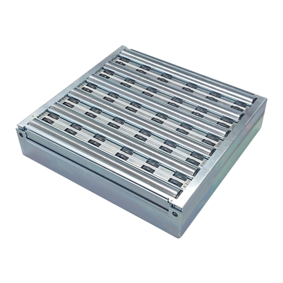
Right Angle Transfer Module
M-RAT
Mighty - Right Angle Transfer
User Manual
Read this manual before use
Thank you for purchasing the Right Angle Transfer Module
(hereinafter referred to as "this product").
*This product refers to all products including standard accessories.
Make sure to read this manual carefully before using, and start
using only after you have understood all the product' s functions,
safety information and precautions.
After reading the manual, make sure to keep it safe in a specified
place for future use, whenever necessary.
ITOH DENKI
ITOH DENKI
ITOH DENKI
Sorting
Module
No.647
Advertisement
Table of Contents

Related Manuals for ITOH DENKI POWER MOLLER PLUS M-RAT


Summary of Contents for ITOH DENKI POWER MOLLER PLUS M-RAT
- Page 1 After reading the manual, make sure to keep it safe in a specified place for future use, whenever necessary. ITOH DENKI ITOH DENKI ITOH DENKI Module...
-
Page 2: Introduction
Features M-RAT User Manual 1. Introduction Features Features of this product ・ This product is a module to transfer trays by diverting at a right angle. Since trays can be diverted at a right angle without changing their level, there will be no impact on the trays. - Page 3 Disclaimer M-RAT User Manual 1. Introduction Disclaimer This product is designed as a general industrial device. Do not use for other ● applications. We do not take any responsibility for any damage that may result from the disregarding of these warnings. In the event that an accident results from the use of this product, we do not ●...
- Page 4 Procedures from installation to operation M-RAT User Manual 1. Introduction Procedures from installation to operation Read this manual Start using only after you have understood all the product’ s functions, safety information, and precautions. Advance preparation Prepare the 24V DC power supply, such as DC power P.12 〜...
-
Page 5: Table Of Contents
INDEX M-RAT User Manual 2. INDEX INDEX Introduction …… 2 INDEX …… 5 Safety precautions …… 7 3-1. General precautions …… 8 3-2. Precautions on installation …… 9 3-3. Precautions on wiring …… 10 3-4. Precautions related to operation …… 10 3-5. Precautions on start-up inspection/maintenance and inspection …… 11 Advance preparation …… 12 Installation/Wiring …… 20... -
Page 6: Safety Precautions
3. Safety precautions M-RAT User Manual 3. Safety precautions For parts names in sentences, refer to Structures (P.18). 3-1. General precautions …… 8 3-2. Precautions on installation …… 9 3-3. Precautions on wiring …… 10 3-4. Precautions related to operation …… 10 3-5. Precautions on start-up inspection/maintenance and inspection …… 11... - Page 7 Danger level M-RAT User Manual M-RAT User Manual 3. Safety precautions To prevent hazards to users and/or others, and/or damage to property in advance, we Danger level explain important precautions to be followed securely as below. ■ The degree of hazard and/or damage that may result if a user disregards the description and operates the product improperly is categorized as the following symbols and explained below.
-
Page 8: General Precautions
General precautions M-RAT User Manual 3. Safety precautions 3-1. WARNING General precautions Do not use the product near places subject to explosive, flammable gas, and/or corrosive atmosphere, and/or combustible materials. Failure to follow this could result in explosion, fire, electric shock and/or injury. When using the product in places where serious accidents and/or damage may possibly occur, install backup and/or fail-safe functions systematically. -
Page 9: Precautions On Installation
General precautions M-RAT User Manual 3. Safety precautions 3-1. CAUTION General precautions Do not turn on/off relays and/or contactors near power cables, signal cables, and/or controllers. Failure to follow this could result in malfunction due to noise generation. LED or Pull-up/Pull-down circuits implemented on the output of control devices could result in unexpected operation. -
Page 10: Precautions On Wiring
Precautions on wiring M-RAT User Manual 3. Safety precautions 3-2. WARNING Precautions on installation Take appropriate measures to prevent trays from popping out of the equipment. For example, mount guide rails on the conveyor frames. Failure to follow this could result in workers getting injured by trays popping out of the equipment. -
Page 11: Precautions On Start-Up Inspection/Maintenance And Inspection
Precautions on start-up inspection/ maintenance and inspection M-RAT User Manual 3. Safety precautions 3-4. CAUTION Precautions related to operation Do not forcibly move trays when they are placed on the product. Failure to follow this could result in damage and/or malfunction. Make sure to perform the start-up inspection before starting operation. -
Page 12: Advance Preparation
4. Advance preparation M-RAT User Manual 4. Advance preparation... - Page 13 Wiring image M-RAT User Manual 4. Advance preparation Wiring image AC power supply Sensor PLC, etc. Controller Breaker SN・S SN・R M-RAT main unit Emergency stop switch CBK-109 CB-016 DC24V Power supply unit CBK-109 Important ・As for the sensor input, and input/output signals of driver cards, adopt the number of inputs/outputs based on your operation needs. Items to be prepared by customers Before introducing this product, prepare the following devices separately.
- Page 14 Items to be prepared by customers M-RAT User Manual 4. Advance preparation Items to be prepared by customers ・A stay used to install the M-RAT main unit. For details on how to mount, refer to P.26. ② Stay (option) ■ Stays, mounting bolts, and washers are not included in the product. Order sepa- rately.
- Page 15 Control devices/Sensors M-RAT User Manual 4. Advance preparation ③ Control devices Devices to control this product, such as PLCs Zone sensors to check the tray, and area sensors to check loading and ④ Sensors discharging, etc. Area sensor (Load) Area sensor (Discharge) M-RAT zone sensor Area sensor (Discharge) Transfer direction Zone sensor...
- Page 16 MDR extension cables (Option) M-RAT User Manual 4. Advance preparation ⑥ MDR extension cables Necessary when the installing location of the M-RAT main unit is far from that of the driver card. (Option) ■ CBK-109:12P extension cable (Male side) Model 12P extension cable length (Female side) ACE-CBM-G0600 L= 600mm ACE-CBM-G1200 L=1200mm...
- Page 17 About the wiring method M-RAT User Manual 4. Advance preparation ⑩ About the wiring method When overcurrent protection devices need to be installed to the 24V DC power supply unit, some ⑩-1 When overcurrent power supplies that need to conform to the safety standards (UL62368-1, etc.) require installation protection devices of the specified overcurrent protection device based on their specifications.
- Page 18 Checking appearance and model/Structures M-RAT User Manual 4. Advance preparation After unpacking, check that there is no abnormalities in the product. Checking appearance ① Check that the main unit is free from any abnormalities, such as traces of scratches, dents, dirt, and/or corrosion (rust). ② Check that there is no omission and/or looseness of screws. If any abnormalities are found, contact the supplier immediately.
- Page 19 Checking accessories M-RAT User Manual 4. Advance preparation Checking accessories Check that all the following items are included. Depending on the M-RAT input and output signal type, driver cards with the NPN (N) Driver card or PNP (P) signal input and output are included. (Not included if driver cards are not specified.) For M−RAT−F□□−□□□□−CN−S1 CBK-109FN...
-
Page 20: Installation/Wiring
5. Installation/Wiring M-RAT User Manual 5. Installation/Wiring 5-1. Before installation・・・ …… 21 5-2. Installation …… 26 5-3. Wiring …… 28 5-4. Connecting to devices …… 31... -
Page 21: Before Installation
Size 6060 M-RAT User Manual 5. Installation/Wiring 5-1. ・When installing the machine, make sure to use the designated stay. ・Prepare stands, and process conveyor frames in advance. Before installation ・Determine the mounting location for zone sensors to check the existence of trays, and area sensors to check loading and discharging. - Page 22 Size 7560 M-RAT User Manual 5. Installation/Wiring Size 7560 L748mm×W580mm 751.2 (Base outer dimension including bead processing) (Reference dimensions) 748 (Base outer dimension) 82.2 (584.2) 175 ( Transfer surface) 114.3 114.3 114.3 114.3 Excluding the protrusion Wiring hole * (751.2) Wiring hole * 553.6 (Pitch between mounting screws) 97.2 *Guide for cable marginal projecting length ...
- Page 23 Size 7570 M-RAT User Manual 5. Installation/Wiring Size 7570 L748mm×W700mm 751.2 (Base outer dimension including bead processing) (Reference dimensions) 748 (Base outer dimension) 82.2 (584.2) 175 ( Transfer surface) 114.3 114.3 114.3 114.3 Excluding the protrusion Wiring hole * (751.2) Wiring hole * 553.6 (Pitch between mounting screws) 97.2 *Guide for cable marginal projecting length ...
- Page 24 Size 7580 M-RAT User Manual 5. Installation/Wiring Size 7580 751.2 (Base outer dimension including bead processing) L748mm×W820mm (Reference dimensions) 748 (Base outer dimension) 82.2 (584.2) 175 ( Transfer surface) 114.3 114.3 114.3 114.3 Excluding the protrusion Wiring hole * (751.2) Wiring hole * 553.6 (Pitch between mounting screws) 97.2 *Guide for cable marginal projecting length ...
- Page 25 Preparation to mount driver cards M-RAT User Manual 5. Installation/Wiring Preparation to mount Hole processing on frames and control panel driver cards ・Perform mounting processing on the frames and control panel by reference to the mounting holes for driver cards. ・ For cable opening and projection from the M-RAT main unit, refer to Mounting preparation for the M-RAT main unit (P.21).
-
Page 26: Installation
Installing the M-RAT main unit M-RAT User Manual 5. Installation/Wiring 5-2. Items to be prepared Installation Stay ● Hanging hook (with lock) ● Cargo handling equipment ● such as hanging belts 3mm hex. wrench 6mm hex. wrench Installing the M-RAT main unit Frame For machine fixing screw Mount stays on conveyor frames. For machine height adjustment screw Recommended tightening torque... - Page 27 Installing the M-RAT main unit M-RAT User Manual 5. Installation/Wiring After checking the machine installation direction, hang the machine and secure it to the stays. Roller transfer direction M-RAT Recommended tightening torque ■ : Carrier wheel roller 25〜29Nm transfer direction Dimension X Dimension Y Type 6060 / 7560 380mm 590〜709mm 7570...
-
Page 28: Wiring
Mounting driver cards M-RAT User Manual 5. Installation/Wiring Mounting driver cards Mounting driver cards Use the included screws and nuts to mount driver cards on the conveyor frames or control panel. Recommended tightening torque: ■ 1.5〜1.9N・m 1.5〜1.9N・m Mounting sensors, Mounting sensors, control devices, and power supply units control devices, and Mount customer-prepared zone sensor and area sensor for loading and discharging, power supply units as well as power supply units, and PLCs. - Page 29 CBK-109 wiring M-RAT 本体とドライバの接続 M-RAT User Manual 5. Installation/Wiring M1: For carrier wheel Wiring for CBK-109 transfer CBK-109 M3: For transfer surface switch 0V OUT CBK-109FN:0V ( ) CBK-109FP:24V 0-10V IN V-IN CBK-109FN:0V ( ) } CBK-109FP:24V ■ Connector description 24V DC (Power) 24V DC Function Detailed description ・Outputs 2 pulse signals for each rotation of the internal motor.
- Page 30 CB-016 wiring M-RAT User Manual 5. Installation/Wiring M2: For roller transfer CB-016 wiring CB-016 0V OUT CB-016BN6:0V ( ) 5.PLS CB-016BP6:24V 4.ERR 0-10V IN 3.V-IN 2.DIR CB-016BN6:0V } ( ) 1.RUN CB-016BP6:24V ■ Connector description DC24V (Power) 24V DC Function Detailed description ・Outputs 2 pulse signals for each rotation of the internal motor. ・NPN open collector output. (NPN output only) Output Motor pulse output...
-
Page 31: Connecting To Devices
Setting driver cards M-RAT User Manual 5. Installation/Wiring Setting driver cards Setting driver cards Check that each driver has the following settings (factory settings). 3.V-IN M1 : CBK-109 2.DIR Minimum Minimum 1.RUN M2 : CB-016 3.V-IN 2.DIR Minimum Minimum 1.RUN M3 : CBK-109 Make sure to use M3: CBK-109 under the following settings. ■... -
Page 32: Control/Operation
6. Control/Operation M-RAT User Manual 6. Control/Operation 6-1. Basic operation …… 34 6-2. Program example …… 35 6-3. Switching the transfer direction …… 36 6-4. Switching the transfer surface …… 37 6-5. Changing the speed …… 38 6-6. What to do before operation …… 40... - Page 33 Device configuration image M-RAT User Manual 6. Control/Operation Device configuration image M-RAT main unit Driver card :CBK-109 CN2#1 Carrier wheel RUN signal transfer MDR :CB 016 :CB-016 CN2#1 Roller transfer MDR RUN signal CN2#1 :CBK-109 RUN signal Transfer surface switch MDR CN2#2 DIR signal SN・S Standby surface signal SN・R Standby surface signal Area sensor for loading...
-
Page 34: Basic Operation
Basic operation M-RAT User Manual 6. Control/Operation 6-1. About control Basic operation M-RAT uses MDR for each of carrier wheel transfer, roller transfer, and ■ transfer surface switch (3 axes in total). Make sure to control to allow each Operation image axis to run independently. (Roller transfer → Carrier wheel transfer) Roller surface standby (SN·R ON) M2: Roller transfer MDR RUN... -
Page 35: Program Example
Program example M-RAT User Manual 6. Control/Operation 6-2. Program example (Operation by loading through carrier wheel transfer and discharging through roller transfer) Program example ■ Do not load trays from the roller transfer direction while the standby status on Operation by loading through the carrier wheel surface is output (signal output from SN·S). carrier wheel transfer and Failure to follow this could result in damage to trays, and malfunction. -
Page 36: Switching The Transfer Direction
Switching the transfer direction M-RAT User Manual 6. Control/Operation 6-3. Switching the transfer direction Switching the transfer Switching the transfer direction can be set using the DIP-SW on the driver card and signal input direction from the control connector. Carrier wheel transfer/ Roller transfer Wiring hole M1: Carrier wheel transfer CCW 〔CBK-109〕... -
Page 37: Switching The Transfer Surface
Switching the transfer surface M-RAT User Manual 6. Control/Operation 6-4. Switching the transfer surface Switching the transfer surface The transfer surface can be switched by inputting the signal to CN2#1 and CN2#2. 〔M3:CBK-109〕 Roller transfer Carrier wheel transfer Roller transfer → Carrier wheel transfer Output CN2#1 CN2#2 Output OUT1 Input SN・R... - Page 38 Changing the speed M-RAT User Manual 6. Control/Operation Internal speed setting External speed setting Set SW1#2 to OFF. Turn SW1#2 ON. Set SW1#5 and SW5. Input the voltage to CN2#3. CN2#3 0〜10V OFF OFF OFF OFF OFF Speed chart ■Nominal speed of 15 m/min type m/min (Speed accuracy: ±3%) SW1#5:ON SW1#5:OFF...
-
Page 39: What To Do Before Operation
Start-up inspection M-RAT User Manual 6. Control/Operation 6-6. To prevent accidents and/or damage to devices during operation, refer in advance and before What to do before operation to the below, and check the safety. operation・・・ Start-up inspection Items to check before turning on the power Turn off the power of all connected devices, and perform the following inspection, taking necessary measures. - Page 40 Commissioning M-RAT User Manual 6. Control/Operation Items to be checked Description of measures Idler/MDR Parts to be inspected Abnormal sound Idler roller for roller transfer Rotation failure Refer to P.44 Abnormal sound 7-2. Before replacement work・・・ MDR for roller transfer Decrease from the specified speed Abnormal temperature rise Abnormal sound Decrease from the specified speed...
- Page 41 7. Maintenance and inspection M-RAT User Manual 7. Maintenance and inspection 7-1. Driver card LED display and error countermeasures …… 42 7-2. Before replacement work …… 44 7-3. Replacement of resin sliders …… 44 7-4. Replacement of idlers/drive belts …… 45 7-5. Replacement of MDR …… 48 7-6. Replacement of the carrier wheel cassette …… 49...
-
Page 42: Driver Card Led Display And Error Countermeasures
〔CBK-109〕Error details M-RAT User Manual 7. Maintenance and inspection 7-1. If errors occur with this product, identify the cause of errors, and perform recovery Driver card LED display work. and error countermeasures Identify the cause of errors by checking LEDs and error signal output on driver cards, Checking the driver card status and restore the product. - Page 43 〔CB-016〕Error details M-RAT User Manual 7. Maintenance and inspection 〔CB-016〕 For roller transfer LED display explanation :Blinking(1 Hz) :Blinking(6 Hz) : : Errors can be checked by PWR (green), ERR (red), and signals from CN2#4. When error signals have been released using CN2#1 (RUN / STOP), the M-RAT instantly ■...
-
Page 44: Before Replacement Work
Replacement of resin sliders M-RAT User Manual 7. Maintenance and inspection 7-2. If any abnormalities are found, such as damaged parts, immediately take actions, Before replacement including replacement with new parts. Product label work・・・ ・Check the model of this product, and FLAT RIGHT ANGLE TRANSFER Product prepare parts to be replaced with in M-RAT- - - - F ... -
Page 45: Replacement Of Idlers/Drive Belts
Replacement of idlers/drive belts M-RAT User Manual 7. Maintenance and inspection 7-4. Replacement of idlers/drive belts Replacement of idlers/ drive belts Remove the top cover. Top cover Tool: 3 mm hex. wrench Remove the MDR connector on the roller unit. ※The actual part is a JST connector. Roller unit Remove the screws used to secure the roller unit. - Page 46 Replacement of idlers/drive belts M-RAT User Manual 7. Maintenance and inspection ① Pull up the pulley part of the idler ② along with the bearing holder, ②Remove the idler and drive belt. Replace with a new idler or drive belt. ① Bearing holder Bearing holder Bearing holder When mounting, ①...
- Page 47 Replacement of idlers/drive belts M-RAT User Manual 7. Maintenance and inspection Align the groove positions of the drive belt. They can be easily aligned by ■ moving the belt while turning the roller. Drive belt Hang the belt Hang the belt Hang the belt over four grooves over one groove over four grooves Mount the roller unit. Have more than one person ■...
-
Page 48: Replacement Of Mdr
Replacement of MDR M-RAT User Manual 7. Maintenance and inspection 7-5. Replacement of MDR Replacement of MDR Remove in the order of , and Perform steps for Replacement of idlers/drive belts, and remove the idlers and drive belts until the drive belt hanging on the MDR comes off. Idler roller Idler roller Idler roller... -
Page 49: Replacement Of The Carrier Wheel Cassette
Replacement of the carrier wheel cassette M-RAT User Manual 7. Maintenance and inspection 7-6. Replacement of the carrier wheel cassette Replacement of the Perform steps for Replacement carrier wheel cassette of idlers/drive belts, and remove the top cover and roller unit. Remove the screws used to secure the carrier wheel cassette to be replaced. Carrier wheel cassette Remove the silver screws. -
Page 50: Troubleshooting
Troubleshooting M-RAT User Manual 8. Troubleshooting... - Page 51 Troubleshooting M-RAT User Manual 8. Troubleshooting If you believe the product may be malfunctioning, check the contents described in this section before contacting us and/or asking for repair. Symptoms M-RAT does not operate Items to be checked Countermeasures References Is PWR LED (Green) for each driver Supply 24V DC.
- Page 52 Troubleshooting M-RAT User Manual 8. Troubleshooting Symptoms Items to be checked Countermeasures References 7. Installation / Is the load conveyor level the same Align levels of the load conveyor Wiring Trays get stuck/Trays as the level of the M-RAT? and the M-RAT. (⇒P.20)...
- Page 53 Troubleshooting M-RAT User Manual 8. Troubleshooting Symptoms ・ The speed cannot be Items to be checked Countermeasures References changed To change the carrier wheel speed, To change the carrier wheel speed, Changing the ・ The speed setting is have you operated the switch on the operate the switch on the driver speed incorrect...
-
Page 54: Appendix
Appendix M-RAT User Manual Appendix... -
Page 55: Appendix 1. Product Specifications
Product specifications M-RAT User Manual Appendix Appendix 1. Product specifications M-RAT main unit specifications Size 6060 7560 7570 7580 748(751.2) (mm) 598(601.2) (mm) Values in ( ) show the base outer dimension 580(586.4) (mm) 580(586.4) (mm) 700(706.4) (mm) 820(826.4) (mm) including bead processing 175 ( mm) (excluding the protrusion part) 80 (... - Page 56 Driver card specifications M-RAT User Manual Appendix Driver card specifications For carrier wheel transfer For roller transfer For transfer surface switch CBK-109F□ CB-016B□6 Model (□=N:NPN, P:PNP) (□=N:NPN, P:PNP) Power supply voltage DC24V±10% Rated voltage DC24V Static current 0.06A 0.03A Starting current 7.0A 4.0A Peak current 30A (1 ms or less) 20A (1ms or less) Power connector 0.80 〜...
-
Page 57: Appendix 2. Residual Risk List/Map
Residual risk list/MAP M-RAT User Manual Appendix Qualifications/ Examples of Measures that Reference Locations Seriousness Operation Appendix 2. education assumed have been taken Remaining risk factors Work page on machine of harm stage required for work measures independently Residual risk list/MAP Dropping the machine due to ・Use the hook with Described in the a disconnected load lifting... - Page 58 ■ ITOH DENKI EUROPE SAS Phone: +33 (0)4 50 03 09 99 Fax: +33 (0)4 50 03 07 60 www.itoh-denki.com North & South America: ■ ITOH DENKI USA, INC Phone: +1 570 820 8811 Fax: +1 570 820 8838 www.itohdenki.com China: ■ ITOH DENKI SHANGHAI CO., LTD. Phone: +86 21 6341 0181 Fax: +86 21 6341 0180 www.itohdenki.com.cn https://www.itohdenki.co.jp Specifications or appearance of product are subject to change without prior notice. Ver.
Need help?
Do you have a question about the POWER MOLLER PLUS M-RAT and is the answer not in the manual?
Questions and answers