Table of Contents
Advertisement
Quick Links
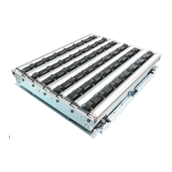
Right Angle Transfer Module
F-RAT-NX75
Flat-Right Angle Transfer
〈 Technical document 〉
Read this manual before use
Thank you for purchasing the Right Angle Transfer Module
(hereinafter referred to as "this product").
〉
e
Make sure to read this manual carefully before using, and start
using only after you have understood all the product' s functions,
safety information and precautions.
After reading the manual, make sure to keep it safe in a specified
place for future use, whenever necessary.
ITOH DENKI
ITOH DENKI
Sorting
Original notice - A1.20
Original
Original notice - A1.20
notice - A1.20
not
Advertisement
Table of Contents

Subscribe to Our Youtube Channel
Related Manuals for ITOH DENKI POWER MOLLER PLUS F-RAT-NX75


Summary of Contents for ITOH DENKI POWER MOLLER PLUS F-RAT-NX75
- Page 1 After reading the manual, make sure to keep it safe in a specified place for future use, whenever necessary. ITOH DENKI ITOH DENKI Original notice - A1.20 Original notice - A1.20 Original notice - A1.20...
-
Page 2: Introduction
Features F-RAT-NX75 Technical document 1. Introduction Features Features of this product ・ This product is a module to divert at a right angle without changing its level, and there is no impact on the trays. ・ All-electric control. No pneumatics, which do not require compressor. Operation description (when diverting at a right angle) - Page 3 Disclaimer F-RAT-NX75 Technical document 1. Introduction Disclaimer This product is designed as a general industrial device. Do not use for other applications. We do not take any responsibility for any damage that may result from the disregarding of these warnings. Also, in the event that an accident results from the use of this product, we do not compensate for any damage, including abnormalities of equipment, connection devices, and/or software, any damage resulting from malfunctions, and/or any other secondary damage.
-
Page 4: Procedures From Installation To Operation
Procedures from installation to operation F-RAT-NX75 Technical document 2. Procedures from installation to operation Procedures from installation to operation Read this manual Start using only after you have understood all the product’ s functions, safety information, and precautions. Advance preparation Prepare the 24V DC power supply, such as DC power supply units. P.15 〜... -
Page 5: Table Of Contents
INDEX F-RAT-NX75 Technical document 2. Procedures from installation to operation INDEX Introduction …… 2 Procedures from installation to operation …… 4 Safety precautions …… 6 3-1. General precautions …… 8 3-2. Precautions on installation …… 10 3-3. Precautions on wiring …… 11 3-4. Precautions related to control …… 11 3-5. -
Page 6: Safety Precautions
3. Safety precautions F-RAT-NX75 Technical document 3. Safety precautions For parts names in sentences, refer to 6. Structures (P.21). 3-1. General precautions …… 8 3-2. Precautions on installation …… 10 3-3. Precautions on wiring …… 11 3-4. Precautions related to control …… 11 3-5. Precautions related to operation …… 12 3-6. - Page 7 Danger level F-RAT-NX75 Technical document 3. Safety precautions Danger level To prevent hazards to users and/or others, and/or damage to property in advance, the important precautions to be followed securely is described below. ■ The degree of hazard and/or damage that may result if a user disregards the description and operates the product improperly is caregorized as the following symbols and explained below.
-
Page 8: General Precautions
General precautions F-RAT-NX75 Technical document 3. Safety precautions WARNING Do not use the product near places subject to explosive, 3-1. flammable gas, and/or corrosive atmosphere, and/or General precautions combustible materials. Failure to follow this could result in explosion, fire, electric shock and/or injury. When using the product in places where serious accidents and/or damage may possibly occur, install backup and/or fail-safe functions systematically. - Page 9 General precautions F-RAT-NX75 Technical document 3. Safety precautions 3-1. CAUTION General precautions Stop operation when abnormal sound is heard during operation. Failure to follow this could result in unexpected accidents. Do not use in a way exceeding the range of the product specifications. Failure to follow this could result in malfunction, fire, and/or injury. Turn off the power supply to the product before moving and/or installing the product, and performing maintenance and inspection (excluding those during operation). Working while the power is on could result in accidents due to unexpected operation. Observe the safety regulations required for installation locations, and/or products in use. Securely wire each cable to connection parts. Improper wiring could result in electric shock and/or malfunction. Do not turn on/off relays and/or contactors near power cables, signal cables, and/or driver cards. Failure to follow this could result in malfunction due to noise generation. LED or Pull-up/Pull-down circuits implemented in the output circuit of control devices could result in unexpected operation. Carefully check the output circuit. Turn on the power of upstream power supplies before turning the product on. Turn off the product before turning the power supplies off. Turning on/off the power in the wrong order could result in malfunction. Do not unplug power and/or signal cables during operation. Also, do not run/stop this product by the power supply. (Use the signal.) Failure to follow this could result in malfunction. Do not forcibly rotate the MDR at times other than maintenance and inspection. Failure to follow this could result in damage to driver cards, and/or their lifetime to be significantly shortened.
-
Page 10: Precautions On Installation
Precautions on installation F-RAT-NX75 Technical document 3. Safety precautions 3-1. CAUTION General precautions Do not turn on the power when trays are unstable. Failure to follow this could result in injury, accidents, and/or damage due to load collapse. Make sure to perform the start-up inspection, and check that devices are free from any abnormalities, and that safety equipment functions correctly before using the product. When disposing of the product, make consigning contracts with licensed industrial waste disposers, and consign the disposal to them. 3-2. WARNING Precautions on installation In principle, have two or more persons work when carrying and/or installing the product as it is a heavy load. To carry the module with Block and tackle please see page 74 for more information. When hoisting this product, never enter the area under the suspended load. When hoisting, use appropriate hoisting equipment, and pay special attention to prevent the balance of the suspended load from being lost and/or falling. -
Page 11: Precautions On Wiring
Precautions on wiring F-RAT-NX75 Technical document 3. Safety precautions 3-2. CAUTION Precautions on installation Take appropriate measures to prevent trays from popping out of the equipment. For example, mount guide rails on the conveyor frames. Failure to follow this could result in workers getting injured by trays popping out of the equipment. -
Page 12: Precautions Related To Operation
Precautions related to operation F-RAT-NX75 Technical document 3. Safety precautions 3-5. CAUTION Precautions related to operation Do not forcibly move trays when they are placed on the carrier wheels. Failure to follow this could result in damage and/or malfunction. Make sure to perform the start-up inspection before starting operation. At the start-up inspection, wear protective equipment, such as gloves. Failure to follow this could result in hands getting injured by metal parts. At the start-up inspection, shut off the power, and perform inspection. (excluding inspection to be performed when operating this product.) Failure to follow this could result in injury due to unexpected operation, such as getting caught and/or stuck. When operating this product at the start-up inspection, take appropriate measures to prevent fingers from getting stuck and/or caught in carrier wheels and/or rollers. Also, get ready to shut off the power in the event that something should happen. Failure to follow this could result in accidents/injury by getting caught and/or stuck. If any abnormalities are found at the start-up inspection, make sure to take countermeasures before the trial run. Failure to follow this could result in damage and/or malfunction. 3-6. CAUTION Precautions on maintenance and If any abnormalities are found, do not use this product until the ... - Page 13 · Check that all parts are installed. Failure to follow this could result in malfunction and/or unexpected accidents. Make sure to prepare repair/replacement parts designated by ITOH DENKI. Using parts other than those designated by ITOH DENKI could result in malfunction. Original notice - A1.20...
-
Page 14: Advance Preparation
4. Advance preparation F-RAT-NX75 Technical document 4. Advance preparation Original notice - A1.20... - Page 15 Emergency stop equipment F-RAT-NX75 Technical document 4. Advance preparation Wiring image Controller, power supply such as PLC Sensors Breaker F-RAT main unit Emergency stop switch CBK-109 CB-016 AC power Sensors source HBM-201 24V DC power unit Breaker F-RAT main unit Emergency stop switch IB-E04F-FT IB-E04F-FT 24V DC power unit HBM-201 As for the sensor input, and input/output signals of driver cards, 【Important】...
- Page 16 24V DC power supply F-RAT-NX75 Technical document 4. Advance preparation 24V DC power supply Power supply equipment to supply 24V DC to this product Operation Since F-RAT uses MDR for each of carrier wheel transfer, roller transfer, ■ and drive switching (3 MDRs in total), it is not recommeded to use multiple MDRs at the same time.
- Page 17 MDR extension cable (option) F-RAT-NX75 Technical document 4. Advance preparation Wiring materials Necessary for wiring of power and signal cables, branch connectors, driver cards, controllers, such as sensors or PLCs, and power supply. 〈Available wire diameter for driver card connectors〉 Driver card CB-016 / HBM-201 CBK-109 Connector Power connector 0.8〜1.5m㎡(AWG:18〜14)...
-
Page 18: Product Check
Product check F-RAT-NX75 Technical document 5. Product check Original notice - A1.20... - Page 19 Checking the model F-RAT-NX75 Technical document 5. Product check Checking the model Unpack the product, and check that the product model is as ordered. FL AT Fー RI GH T AN Tー T A A ED IN ー F6 E TR T: DC SE RIA D: m 0...
- Page 20 Checking accessories F-RAT-NX75 Technical document 5. Product check Checking accessories Check that all the following items are included. Driver cards Depending on the F-RAT input and output signal type, driver cards with the NPN (N) or PNP (P) signal input are included. (Not included when no driver card type is specified.) For F−RAT−NX75−□□□−□□□□−CN CBK-109FN CB-016BN7...
-
Page 21: Structures
Structures F-RAT-NX75 Technical document 6. Structures Original notice - A1.20... - Page 22 Product designation F-RAT-NX75 Technical document 6. Structures Structures Carrier wheel transfer MDR(M1) Roller transfer MDR(M2) Drive switching MDR(M3) Idler( 48.6) ( 48.6) Drive belt Carrier wheel FL AT R IG Fー H T Idler( 38) Tー TE D G LE IN PU T RA Carrier wheel cassette ー...
-
Page 23: Installation/Wiring
Installation/Wiring F-RAT-NX75 Technical document 7. Installation/Wiring 7-1. Before installation …… 24 7-2. Installation …… 33 7-3. Wiring …… 35 Original notice - A1.20... -
Page 24: Before Installation
Size 6040・6050 F-RAT-NX75 Technical document 7. Installation/Wiring 7-1. ・Prepare stands, and perform frame processing in advance by reference to the mounting holes in dimensions. Before installation ・Determine the mounting location for zone sensors to check the existence of trays, and area sensors to check loading and discharging. Then, prepare for them to be mounted. Min and max size load ・Minimum load size : 225 x 225mm ・Maximum load size : -100mm from the length and the width of F-RAT-NX75. - Page 25 Size 6060・6070 F-RAT-NX75 Technical document 7. Installation/Wiring Size 6060 L595mm×W595mm (Mounting nut position) 22.5 22.5 * Cable (Pipe size) *Guide for cable marginal projecting length (mm) 4 × Mounting nut(M8) M1 : Carrier wheel transfer MDR 1000 M2 : Roller transfer MDR M3 : Drive switching MDR 1300 Size 6070 L595mm×W695mm (Mounting nut position) 22.5 22.5 * Cable (Pipe size) 4 × Mounting nut(M8) *Guide for cable marginal projecting length (mm) M1 : Carrier wheel transfer MDR 1000 M2 : Roller transfer MDR M3 : Drive switching MDR 1300 Original notice - A1.20...
- Page 26 Size 6080・7540 F-RAT-NX75 Technical document 7. Installation/Wiring Size 6080 (Mounting nut position) L595mm×W795mm 22.5 22.5 * Cable (Pipe size) 4 × Mounting nut(M8) *Guide for cable marginal projecting length (mm) M1 : Carrier wheel transfer MDR 1000 M2 : Roller transfer MDR M3 : Drive switching MDR 1300 Size 7540 (Mounting nut position) L745mm×W395mm 22.5 22.5 * Cable 4 × Mounting nut(M8) *Guide for cable marginal projecting length (mm) M1 : Carrier wheel transfer MDR 1200 M2 : Roller transfer MDR 1100 M3 : Drive switching MDR 1200 Original notice - A1.20...
- Page 27 Size 7550・7560 F-RAT-NX75 Technical document 7. Installation/Wiring Size 7550 L745mm×W495mm (Mounting nut position) 22.5 22.5 * Cable *Guide for cable marginal projecting length (mm) 4 × Mounting nut(M8) M1 : Carrier wheel transfer MDR M2 : Roller transfer MDR 1000 M3 : Drive switching MDR 1200 Size 7560 L745mm×W595mm (Mounting nut position) 22.5 22.5 * Cable 4 × Mounting nut(M8) *Guide for cable marginal projecting length (mm) M1 : Carrier wheel transfer MDR M2 : Roller transfer MDR M3 : Drive switching MDR 1200 Original notice - A1.20...
- Page 28 Size 7570・7580 F-RAT-NX75 Technical document 7. Installation/Wiring Size 7570 (Mounting nut position) L745mm×W695mm 22.5 22.5 * Cable *Guide for cable marginal projecting length (mm) 4 × Mounting nut(M8) M1 : Carrier wheel transfer MDR M2 : Roller transfer MDR M3 : Drive switching MDR 1200 Size 7580 (Mounting nut position) L745mm×W795mm 22.5 22.5 * Cable (Pipe size) *Guide for cable marginal projecting length (mm) 4 × Mounting nut(M8) M1 : Carrier wheel transfer MDR M2 : Roller transfer MDR M3 : Drive switching MDR 1200 Original notice - A1.20...
- Page 29 Size 9040・9050 F-RAT-NX75 Technical document 7. Installation/Wiring Size 9040 (Mounting nut position) L895mm×W395mm 22.5 22.5 * Cable 4 × Mounting nut(M8) *Guide for cable marginal projecting length (mm) M1 : Carrier wheel transfer MDR M2 : Roller transfer MDR 1100 M3 : Drive switching MDR 1100 Size 9050 L895mm×W495mm (Mounting nut position) 22.5 22.5 * Cable 4 × Mounting nut(M8) *Guide for cable marginal projecting length (mm) M1 : Carrier wheel transfer MDR M2 : Roller transfer MDR 1000 M3 : Drive switching MDR 1100 Original notice - A1.20...
- Page 30 Size 9060・9070 F-RAT-NX75 Technical document 7. Installation/Wiring Size 9060 L895mm×W595mm (Mounting nut position) 22.5 22.5 * Cable (Pipe size) 4 × Mounting nut(M8) *Guide for cable marginal projecting length (mm) M1 : Carrier wheel transfer MDR M2 : Roller transfer MDR M3 : Drive switching MDR 1100 Size 9070 L895mm×W695mm (Mounting nut position) 22.5 22.5 * Cable *Guide for cable marginal projecting length 4 × Mounting nut(M8) (mm) M1 : Carrier wheel transfer MDR M2 : Roller transfer MDR M3 : Drive switching MDRV 1100 Original notice - A1.20...
- Page 31 Size 9080 F-RAT-NX75 Technical document 7. Installation/Wiring Size 9080 L895mm×W795mm (Mounting nut position) 22.5 22.5 * Cable (Pipe size) 4 × Mounting nut(M8) *Guide for cable marginal projecting length (mm) M1 : Carrier wheel transfer MDR M2 : Roller transfer MDR M3 : Drive switching MDR 1100 Original notice - A1.20...
- Page 32 Mounting preparation for driver cards F-RAT-NX75 Technical document 7. Installation/Wiring Mounting preparation Hole processing on frames and control panel for driver cards ・Perform mounting processing on the frames and control panel by reference to the mounting holes for driver cards. ・For cable opening and projection from the F-RAT main unit, refer to Mounting preparation for the F-RAT main unit (P.24).
-
Page 33: Installation
Installing the F-RAT main unit F-RAT-NX75 Technical document 7. Installation/Wiring 7-2. Necessary tools Installation 13mm Phillips head screwdriver Precision slotted ratchet wrench screwdriver Stripper (No.2) Installing the Installing the F-RAT main unit F-RAT main unit Carry this product to the installing location. When lifting, hold the bottom of this product. ■... - Page 34 About stays (option)) F-RAT-NX75 Technical document 7. Installation/Wiring About stays (option) Dedicated stay (optional) is prepared for F-RAT installation. ■ If users do not use the stays, be sure to use the mounting holes on the F-RAT main unit to secure the F-RAT. In addition, comply with the mounting dimensions for stays, as well as mount them by taking into consideration the weight of this product and trays.
-
Page 35: Wiring
Wiring F-RAT-NX75 Technical document 7. Installation/Wiring Mounting driver cards Mounting driver cards Use the included screws and nuts to mount driver cards on the conveyor frames or control panel. Recommended tightening torque: ■ 1.5 to 1.9N·m 1.5〜1.9N m Mounting sensors, Mounting sensors, control devices, and power supply units control devices, and Mount customer-prepared zone sensor and area sensor for loading and discharging, power supply units as well as power supply units, and PLCs. - Page 36 Wiring for CBK-109 F-RAT-NX75 Technical document 7. Installation/Wiring Wiring for CBK-109 〔CBK-109〕 CBK-109 M1:For carrier wheel transfer CBK-109FN:0V ( ) } CBK-109FP:24V 0-10V IN V-IN CBK-109FN:0V } ( ) CBK-109FP:24V ■ Connector descriptions DC24V (Power) DC24V Functions Detailed descriptions ・Outputs 2-pulse signal per rotation of the internal motor. NPN open collector output.
- Page 37 Wiring for CB-016 F-RAT-NX75 Technical document 7. Installation/Wiring Wiring for CB-016 〔CB-016〕 CB-016 M2:For roller transfer CB-016BN7:0V ( ) } 5.PLS CB-016BP7:24V 4.ERR 0-10V IN 3.V-IN 2.DIR CB-016BN7:0V } ( ) 1.RUN CB-016BP7:24V DC24V ■ Connector descriptions (Power) DC24V Functions Detailed descriptions ・Outputs 2-pulse signal per rotation of the internal motor. Motor pulse NPN open collector output.
- Page 38 Wiring for HBM-201 F-RAT-NX75 Technical document 7. Installation/Wiring 〔HBM-201〕 Wiring for HBM-201 M3:For drive switching HBM-201 DC24V 1 2 3 4 5 HBM-201BN:0V ( ) } ■ Connector descriptions HBM-201BP:24V HBM-201BN:0V ( ) } HBM-201BP:24V (Power) DC24V Functions Detailed descriptions Carrier wheel surface ・Carrier wheel and roller transfer surface are switched by inputting Input switch input signal...
- Page 39 Setting driver cards F-RAT-NX75 Technical document 7. Installation/Wiring Setting driver cards Settings for M1: CBK-109/M2: CB-016 Turn the driver card volume to the following (factory setting). 3.V-IN 2.DIR 1.RUN Minimum Minimum Settings for M3: HBM-201 Turn the driver card DIP switch and rotary switch to the following (factory setting). HBM−201B□ OFF OFF OFF OFF OFF OFF OFF OFF OFF OFF OFF HBM-201BP...
-
Page 40: Control/Operation
8. Control/Operation F-RAT-NX75 Technical document 8. Control/Operation 8-1. Basic operation …… 42 8-2. Switching the transfer direction …… 46 8-3. Changing the speed …… 47 8-4. Switching the transfer surface …… 49 8-5. About the initial position setting (teaching) of the transfer surface …… 50 8-6. Program example …… 51 8-7. - Page 41 Device configuration image F-RAT-NX75 Technical document 8. Control/Operation Device configuration This product image F-RAT main unit Driver cards CBK-109 CN2#1 Carrier wheel RUN signal transfer MDR CB-016 CB 016 CN2#1 Roller transfer MDR RUN signal HBM-201 CN2#4, #5 Drive switching MDR Switch signal CN2#1, #2 Standby surface signal Area sensor for loading...
-
Page 42: Basic Operation
Basic operation F-RAT-NX75 Technical document 8. Control/Operation 8-1. About control Basic operation F-RAT uses MDR for each of carrier wheel transfer, roller transfer, and trans- ■ fer surface switch (3 axes in total). Make sure to control to allow each axis to Operation image run independently. - Page 43 Basic operation F-RAT-NX75 Technical document 8. Control/Operation 8-1. Set the initial Transfer surface Transfer surface Turn on Load Discharge Basic operation position of the switch switch the power transfer surface (Prepare reception) The following operation is for when the rotation direction setting SW1#3 for ■...
- Page 44 Basic operation F-RAT-NX75 Technical document 8. Control/Operation Set the initial Transfer surface Transfer surface Turn on Load Discharge position of the switch switch the power transfer surface (Prepare reception) Zone sensor for the discharge Area sensor Load conveyor for discharging F-RAT zone sensor On the side of M2:CB-016 V-ribbed pulley...
- Page 45 Basic operation F-RAT-NX75 Technical document 8. Control/Operation Set the initial Transfer surface Transfer surface Turn on Load Discharge position of the switch switch the power transfer surface (Prepare reception) Zone sensor for the discharge Area sensor Discharge conveyor for discharging F-RAT zone sensor On the side of M1:CBK-109 V-ribbed pulley...
-
Page 46: Switching The Transfer Direction
Switching the transfer direction F-RAT-NX75 Technical document 8. Control/Operation 8-2. Switching the transfer direction Switching the The transfer direction can be set by DIP-SW on the driver card, and signal input. transfer direction ■ When changing the direction, check the F-RAT main unit installation direction. 〔M1:CBK-109 / M2:CB-016〕 ■... - Page 47 Changing the transfer speed F-RAT-NX75 Technical document 8. Control/Operation 8-3. Changing the transfer speed Changing the There are two types of settings to change speed: the internal speed setting to change transfer speed the speed by switches on the driver card, and the external speed setting to change the 〔M1:CBK-109 / M2:CB-016〕...
-
Page 48: Changing The Speed
Changing the speed F-RAT-NX75 Technical document 8. Control/Operation 8-3. Changing the speed 〔M1:CBK-109 / M2:CB-016〕 Speed chart [M1:Carrier wheel speed] Speed accuracy: ±3% (m/min) SW1#5:ON SW1#5:OFF Setting 61.5 56.4 53.9 51.3 48.7 46.2 41.1 38.4 35.9 33.4 30.8 28.2 25.6 23.1 20.5 18.0 15.5 12.8 10.3 7.7... -
Page 49: Switching The Transfer Surface
Switching the transfer surface F-RAT-NX75 Technical document 8. Control/Operation 8-4. Switching the transfer surface Switching the The transfer surface can be switched by inputting the signal to CN2#4 and CN2#5. transfer surface After the initial position setting (teaching) of the transfer surface, the roller surface is ■... -
Page 50: About The Initial Position Setting (Teaching) Of The Transfer Surface
teaching F-RAT-NX75 Technical document 8. Control/Operation 8-5. About the initial position setting (teaching) of the transfer surface About the initial position The initial position setting (teaching) of the transfer surface is necessary to set the setting (teaching) transfer surface after the power is turned on. of the transfer surface ■ If teaching has not been set, the transfer surface cannot be switched. 〔M3:HBM-201〕... -
Page 51: Program Example
Program example F-RAT-NX75 Technical document 8. Control/Operation 8-6. Program example Program example ■ Do not load trays from the roller transfer MDR direction while the carrier wheel Operation by loading through status (signal from CN2#2 on HBM-201) is output. roller transfer and discharging Failure to follow this could result in damage to trays, and malfunction. through carrier wheel transfer The following time chart is an example. -
Page 52: What To Do Before Operation
Start-up inspection F-RAT-NX75 Technical document 8. Control/Operation 8-7. To prevent accidents and/or damage to devices during operation, refer to the below before operation, and check the safety. What to do before operation Items to check before turning on the power Start-up inspection Turn off the power of all connected devices, and perform the following inspection, taking necessary measures. - Page 53 Trial run F-RAT-NX75 Technical document 8. Control/Operation Trial run Items to check before the trial run Check below before the trial run. ・When the roller transfer MDR and/or idlers have been replaced, check that the drive belts have been mounted in the correct groove positions. ・Check all parts are installed. Performing the trial run When the start-up inspection has finished, perform the trial run with careful attention to the following points, and check that operation is correctly performed.
-
Page 54: Maintenance/Inspection
9. Maintenance/Inspection F-RAT-NX75 Technical document 9. Maintenance/Inspection 9-1. Driver card LED display and error countermeasures …… 55 9-2. Before replacement work …… 58 9-3. Replacement of MDR for roller transfer/idlers/roller drive belts …… 60 9-4. Replacement of the carrier wheel cassette …… 65 Original notice - A1.20... -
Page 55: Driver Card Led Display And Error Countermeasures
〔CBK-109〕Error details F-RAT-NX75 Technical document 9. Maintenance/Inspection 9-1. If errors occur with this product, identify the cause of errors, and perform recovery Driver card LED display work. and error countermeasures Checking the Identify the cause of errors by checking LEDs and error signal output on driver cards, driver card status and restore the product. - Page 56 〔CB-016〕Error details F-RAT-NX75 Technical document 9. Maintenance/Inspection 〔CB-016〕 For roller transfer :ON :Blinking (1Hz) :Blinking (6Hz) :OFF LED display explanation Errors can be checked by PWR (Green), ERR (Red), and signals from CN2#4. When error signals have been released by CN2#1 (RUN / STOP), the F-RAT instantly ■...
- Page 57 〔HBM-201〕Error details F-RAT-NX75 Technical document 9. Maintenance/Inspection Even if inputting the signal to CN2#4 and #5, but the signal output from CN2#1 and #2 〔HBM-201〕 does not change, the following errors have been assumed to occur. Errors can be For switching the distinguished by the LED display. transfer surface LED display explanation :Blinking (1Hz)...
-
Page 58: Before Replacement Work
Replacement parts F-RAT-NX75 Technical document 9. Maintenance/Inspection 9-2. If any abnormalities, such as damaged parts, are found, immediately take actions, including replacement with new parts. Before replacement Product label work ・Check the model of this product, and prepare parts to be replaced with in Model advance. - Page 59 Replacement parts F-RAT-NX75 Technical document 9. Maintenance/Inspection Width Speed / Ø Length L for all Itoh Denki reference Parts name size (40 80) PM486FE0600542XRNT N000 60XX All width 60m/min MDR for All width PM486FE0600692XRNT N000 75XX 60m/min roller transfer PM486FE0600842XRNT N000 All width...
- Page 60 Replacement of roller transfer MDR/idlers F-RAT-NX75 Technical document 9. Maintenance/Inspection If any abnormalities are found in one of the roller transfer MDR, idlers, and/or 9-3. Replacement of roller drive belts, replace them according to the following methods. roller transfer MDR/idlers /roller drive belts Before replacement Before replacement, prepare necessary tools.
- Page 61 Replacement of roller transfer MDR/idlers F-RAT-NX75 Technical document 9. Maintenance/Inspection Replacement procedures Slide the spring loaded shaft from the fixed hole(①), and remove the idler from the frame (②) <Figure seen from the side> Frame Fixed hole ①Push the spring loaded shaft ②Remove it from until it has passed through the the frame fixed hole...
- Page 62 Replacement of roller transfer MDR/idlers F-RAT-NX75 Technical document 9. Maintenance/Inspection Replacement procedures Lift up the tip of the roller transfer ②Remove the roller drive belt MDR (①), and remove the roller drive belt. (②) Remove the roller ①Lift up transfer MDR (③), and pull the power cable off the fixed hole on the frame (④)...
- Page 63 Replacement of roller transfer MDR/idlers F-RAT-NX75 Technical document 9. Maintenance/Inspection Replacement procedures Mount the roller drive belt on the V-ribbed pulley of the roller transfer MDR (①), align the tip of the attaching shaft with the ①Mount the roller notch shape, and fit it into the drive belt frame (②)...
- Page 64 Replacement of roller transfer MDR/idlers F-RAT-NX75 Technical document 9. Maintenance/Inspection Replacement procedures Align the tip of the attaching shaft on the side of the belt on the V-ribbed pulley, where the roller drive belt has been mounted, with the notch shape on the frame, Attaching shaft and fit it into the frame ■Press the D-shaped cut surface...
-
Page 65: Replacement Of The Carrier Wheel Cassette
Replacement of the carrier wheel cassette F-RAT-NX75 Technical document 9. Maintenance/Inspection If any abnormalities are found in the carrier wheels, replace the whole carrier 9-4. wheel cassette. Replacement of the carrier wheel cassette Before replacement Before replacement, prepare necessary tools. Tools to be used 8 mm/19 mm wrench 5 mm hex. - Page 66 Replacement of the carrier wheel cassette F-RAT-NX75 Technical document 9. Maintenance/Inspection Replacement procedures Mounting the carrier wheel cassette on the F-RAT main unit Check the model of the removed On the side of V-ribbed pulley carrier wheel cassette and replacement carrier wheel cassette. Location of the Indication example) carrier wheel cassette NX-75CC 75A model indication This part of the carrier wheel cassette is indicated on the product.
-
Page 67: Troubleshooting
Troubleshooting F-RAT-NX75 Technical document 10. Troubleshooting Original notice - A1.20... - Page 68 F-RAT does not operate F-RAT-NX75 Technical document 10. Troubleshooting If you believe the product may be malfunctioning, check the contents described in this section before contacting the supplier and/or asking for repair. Symptoms F-RAT does not operate Items to be checked Countermeasures References Is PWR LED (Green) for each Supply 24V DC.
- Page 69 Trays get stuck/Trays cannot be transferred F-RAT-NX75 Technical document 10. Troubleshooting Symptoms When loading, Items to be checked Countermeasures References trays get stuck, or 7. Installation/ cannot be transferred Is the load conveyor level the Align levels of the load conveyor Wiring same as the level of the F-RAT? and the F-RAT.
- Page 70 The speed cannot be changed F-RAT-NX75 Technical document 10. Troubleshooting Symptoms ・The speed cannot be Items to be checked Countermeasures References changed To change the carrier wheel To change the carrier wheel Changing the ・The speed setting is transfer speed speed, have you operated the speed, operate the switch on incorrect (⇒P.47)...
-
Page 71: Appendix
Appendix F-RAT-NX75 Technical document Appendix Original notice - A1.20... -
Page 72: Appendix 1. Product Specifications
F-RAT main unit specifications F-RAT-NX75 Technical document Appendix Appendix 1. Product specifications F-RAT main unit specifications Size 60□□ 6040 6050 6060 6070 6080 Total length (L) Carrier wheel transfer direction 595mm F-RAT Total width (W) Roller transfer direction 395mm 495mm 595mm 695mm 795mm main unit Weight 32kg... - Page 73 Driver card specifications F-RAT-NX75 Technical document Appendix Appendix 1. Product specifications Driver card specifications For carrier wheel transfer For roller transfer For drive switching CBK-109F□ CB-016B□7 HBM-201B□ Model (□=N:NPN, P:PNP) (□=N:NPN, P:PNP) (□=N:NPN, P:PNP) Power supply voltage 24V DC±10% Rated voltage 24V DC Static current 0.06A 0.03A...
- Page 74 Failure to follow this could result in its lifetime to be signifi- cantly shortened. Appendix 2. Options Carrier wheel cassette Length Width Speed / Ø Itoh Denki reference NX75-CC60X 60XX All width (X: A, B, C or D)* NX75-CC75X All width 75XX...
-
Page 75: Appendix 3. Residual Risk List/Map
Residual risk F-RAT-NX75 Technical document Appendix 【Seriousness of harm】 Appendix 3. WARNING: Indicates that there is a possibility that severe injury or even death may result if protective measures have Residual risk list/MAP not been taken CAUTION: Indicates that there is a possibility that minor injury may result if protective measures have not been taken Residual risk list Qualifications/ Measures that... -
Page 76: Appendix 4. Transfer Capacity
Transfer capacity F-RAT-NX75 Technical document Appendix Appendix 4. Transfer capacity Transfer time Receiving time Transfer surface Discharge time Transfer time (sec) exchange cycle time (sec) (sec) Package length (mm) One cycle time = 1,10 sec Discharge time (graph 1) + From reception of the (Transfer speed* (m/min) /60) x 1000 additional time depending on the package until the next... -
Page 77: Appendix 5. Incorporation Declaration
• Machinery Directive 2006/42/EC • European EMC Directive 2014/30/EC • European RoHS Directive 2011/65/EU ITOH DENKI EUROPE SAS, undertakes to forward, following a duly motivated request from the national authorities, the relevant information concerning the quasi-machine. Saint Pierre en Faucigny, 19 July 2021 T. - Page 78 Technology for tomorrow ITOH DENKI 490 Av. des Jourdies - P.A.E. les Jourdies 74800 St Pierre en Faucigny - France Phone : +33 (0)4 50 03 09 99 Fax : +33 (0)4 50 03 07 60 www.itoh-denki.com Original notice - A1.20...
Need help?
Do you have a question about the POWER MOLLER PLUS F-RAT-NX75 and is the answer not in the manual?
Questions and answers