Advertisement
Quick Links
Advertisement

Related Manuals for Klimaire FIT PRO Series


Summary of Contents for Klimaire FIT PRO Series
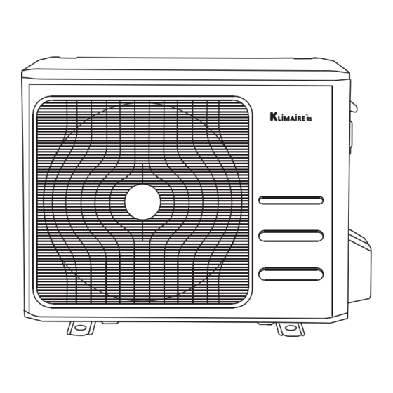
- Page 1 KIDF/KOIF FIT PRO SERIES OUTDOOR UNIT AIR CONDITIONER Installation Manual Safety precutions & Installation IMPORTANT NOTE: Read this manual carefully before installing or operating your new air conditioning unit. Make sure to North America Products save this manual for future reference.
-
Page 2: Table Of Contents
INSTALLATION MANUAL SAFETY PRECAUTIONS ACCESSORIES REFRIGERANT PIPING CONNECTION OUTDOOR UNIT INSTALLATION WIRING SPECIFICATION AIR EVACUATION NOTE ON ADDING REFRIGERANT TEST RUN Read this manual Inside you’ll find many helpful hints on how to use and maintain your air conditioner properly. Just a little preventive care on your part can save you a great deal of time and money over the life of your air conditioner. -
Page 3: Safety Precautions
SAFETY PRECAUTIONS Intended Use The following safety guidelines are intended to prevent unforeseen risks or damage from unsafe or incorrect operation of the appliance. Please check the packaging and appliance on arrival to make sure everything is intact to ensure safe operation. If you find any damage, please contact the retailer or dealer. - Page 4 WARNINGS FOR PRODUCT USE • If an abnormal situation arises (like a burning smell), immediately turn off the unit and disconnect the power. Call your dealer for instructions to avoid electric shock, fire or injury. • Do not insert fingers, rods or other objects into the air inlet or outlet. This may cause injury, since the fan may be rotating at high speeds.
- Page 5 ELECTRICAL WARNINGS Do not share the electrical circuit with other appliances. This equipment requires a dedicated • electrical circuit. • The product must be properly grounded at the time of installation, or electrical shock may occur. • For all electrical work, follow all local and national wiring standards, regulations, and the Installation Manual.
- Page 6 TAKE NOTE OF FUSE SPECIFICATIONS The air conditioner’s circuit board (PCB) is designed with a fuse to provide overcurrent protection. This fuse must be replaces with identical component. The specifications of the fuse are printed on the circuit board ,examples of such are T5A/250VAC and T10A/250VAC.
-
Page 7: Accessories
ACCESSORIES The air conditioning system comes with the following accessories. Use all of the installation parts and accessories to install the air conditioner. Improper installation may result in water leakage, electrical shock and fire, or equipment failure. Accessories (Packed with the indoor unit) Name Shape Quantity... -
Page 8: Refrigerant Piping Connection
REFRIGERANT PIPING CONNECTION Safety Precautions WARNING • All field piping must be completed by a licensed technician and must comply with the local and national regulations. • When the air conditioner is installed in a small room, measures must be taken to prevent the refrigerant concentration in the room from exceeding the safety limit in the event of refrigerant leakage. - Page 9 Name Shape Quantity(PC) 6.35( 1/4 i n) Liquid side 9.52( 3/8in) The correct connecting Connecting pipe 12.7( 1/2in) pipes are included with assembly your equipment. 16( 5/8in) Gas side 19( 3/4in) 22( 7/8in) Air Handler Unit Air Handler Unit Adapter Required at Outdoor Outdoor Unit Adapter Required...
- Page 10 Connection Instructions—Refrigerant Piping CAUTION • The branching pipe must be installed horizontally. An angle of more than 10° may cause malfunction. DO NOT install the connecting pipe until both indoor and outdoor units have been installed. • • Insulate both the gas and liquid piping to prevent condensation. Step 1: Cut pipes Step 2: Remove burrs When preparing refrigerant pipes, take...
- Page 11 Outdoor unit Liquid side piping (Smaller diameter) • Clamp flare from on the end of the pipe. The end of the pipe must extend beyond the flare form. (Bigger Flare form Pipe • Place flaring tool onto the form. Torque wrench •...
-
Page 12: Outdoor Unit Installation 1
OUTDOOR UNIT INSTALLATION NOTICE Install the unit by following local switchs and regulations , there may be differ slightly between different regions. Select the installation location of outdoor units Before installing the outdoor unit, you must choose an appropriate location. The following are standards that will help you choose an appropriate location for the unit. - Page 13 Install drain fitting(Heat pump unit only) Base pan hole of outdoor unit Step 1: Find out the base pan hole of outdoor unit. Seal Step 2: Fit the rubber seal on the end of the drain fitting that will connect to the ●...
- Page 14 Anchor outdoor unit The outdoor unit can be anchored to the ground or to a wall-mounted bracket with bolt(M10). Prepare the installation base of the unit according to the dimensions below. Outdoor Unit Types and Specifications Front view Top view Outdoor Unit Dimensions Mounting Dimensions inch...
- Page 15 If you will install the unit on the ground If you will install the unit on a wall-mounted bracket, or on a concrete mounting platform, DO THE FOLLOWING: DO THE FOLLOWING: Mark the positions for four expansion bolts Mark the position of bracket holes based on ●...
- Page 16 WIRING PRECAUTIONS WARNING BEFORE PERFORMING ANY ELECTRICAL WORK, READ THESE WARNINGS. All wiring must comply with local and national Do not let wires touch or rest against ● ● electrical codes, regulations and must be installed refrigerant tubing, the compressor, or any by a licensed electrician.
- Page 17 OUTDOOR UNIT WIRING WARNING Before performing any electrical or wiring work, turn off the main power to the system. Step 1: Prepare the cable for connection. 1. You must first choose the right cable size. 2. Using wire strippers, strip the jacket from CLASS 2 both ends of the signal cable to reveal B W D...
- Page 18 Please ensure that thermostat configuration noise transmitted onto the signal wires. is set up for B functionality. Note: These methods are for use with a Klimaire outdoor unit and a third party indoor unit or cased coil and gas furnace.
- Page 19 Klimaire Fit Pro AHU wiring connec on & deep witch configurara on guide Klimaire AHU Klimaire ODU Connecton between Indoor DIP switch DIP switch Scenario Controller Indoor unit Outdoor unit SW1-1 SW1-4 S1-2 Scenario 1 Klimaire Wired Klimaire AHU RS485: S1/S2...
- Page 20 Scenario 2: S1/S2 Klimaire AHU Indoor unit 24V Thermostat Klimaire Outdoor unit S1/S2 SW1- 1 dip switch to be "ON" Nest 24V thermostat as a example Note: Need to set the dip switch before the S4-1 Default on, W1 and W2 unit power on.
- Page 21 SPECIFIC WIRING METHODS NOTICE The following wiring diagram are suitable for the AHU and ODU with 24V thermostat. Non-communication scheme wiring reference • Wiring for 4H and 2C thermostat • Wiring for 3H and 2C thermostat W1/E W1/E THERMOSTAT W1 W2 Y1 Y2 B W D THERMOSTAT...
- Page 22 • Wiring for 1H and 1C thermostat Control logic Indoor unit connector Connector Purpose 24V power Connection THERMOSTAT Common W1 W2 Y1 Y2 B W D Low Cooling INDOOR UNIT OUTDOOR UNIT Heat Cooling Heating Reversing Valve • Wiring for 1H and 1C thermostat Heating control Defrost control System Fault Signal...
- Page 23 POWER SPECIFICATIONS Cooling and Heating power specifications PHASE POWER (outdoor) FREQUENCY AND VOLT Hyper HT Hyper HT Hyper HT OUTDOOR UNIT(A) INPUT CIRCUIT FUSE / 16 / 20 / 23 20 / MOCP 30 / 35 / 2+Ground LINE QUANTITY OUTDOOR UNIT POWER LINE LINE DIAMETER(AWG)
-
Page 24: Air Evacuation
AIR EVACUATION NOTICE When opening valve stems, turn the hexagonal wrench until it hits against the stopper. Do not try to force the valve to open further. open valves slowly until your hear refrigerant, allow pressure to equalize before opening fully. Open large vapor line valve first. -
Page 25: Note On Adding Refrigerant
NOTE ON ADDING REFRIGERANT CAUTION DO NOT mix refrigerant types. Some systems require additional charging depending on pipe lengths. The standard pipe length varies according to local regulations. For example, in North America, the standard pipe length is 7.5m (25’). In other areas, the standard pipe length is 5m (16‘). -
Page 26: Test Run
TEST RUN CAUTION Failure to perform the test run may result in unit damage, property damage, or personal injury. 5. For the Outdoor Unit Before test run a. Check to see if the refrigeration system is leaking. A test run must be performed after the entire b. - Page 27 The Klimaire logo is a registered Trademark of Klimaire Products inc. Copyright 2023 Klimaire Products Inc. 2190 NW 89 Place, Doral, FL 33172 - USA Tel: (305)593-8358 Fax (305) 675-2212 www.klimaire.com sales@klimaire.com The design and specifications are subject to change without prior notice for product improvement.
Need help?
Do you have a question about the FIT PRO Series and is the answer not in the manual?
Questions and answers