Table of Contents
Advertisement
Quick Links
Advertisement
Table of Contents

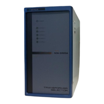
Summary of Contents for Amada MA-650A
- Page 1 TRANSFORMER SELECTOR MA-650A OPERATION MANUAL Y02M0774E-07...
-
Page 2: Table Of Contents
MA-650A Thank you for purchasing our Transformer Selector MA-650A. ・For correct use, read this operation manual carefully. ・After reading, save it in a proper place where you can easily access to. Contents 1. Special Precautions (1) Safety Precautions ············································································· 1-1 (2) Precautions for Handling ·····································································... -
Page 3: Special Precautions
MA-650A 1. Special Precautions (1) Safety Precautions CAUTION ! Before using, read "Safety Precautions" carefully to understand the correct Denotes operations and practices that method of use. may result in personal injury or damage to the equipment if not correctly followed. - Page 4 MA-650A W ARNING Do not put your hands between the electrodes. When welding, keep your fingers and hands away from the electrodes. Do not touch any welded part or electrodes during welding and just after welding finished. The welded part of a workpiece, electrodes and arm are very hot.
- Page 5 MA-650A CAUTIO N Connect the cords and cables securely. Loose connection can cause fire and electric shock. Do not splash water on the equipment. Water splashed over the electric parts, can cause electric shock and short circuits. Use proper tools (wire strippers, pressure wire connectors, etc.) for termination of the connecting cables.
-
Page 6: Precautions For Handling
MA-650A (2) Precautions for Handling When transporting or moving the Selector, do not lay it down. Also, handle the Selector with care so as not to make an impact such as drop on it. Install the Transformer Selector on a firm and level surface. If it is used inclined or on its side, it may have a malfunction. -
Page 7: Features
I/O connector (4.(2)④ [SENS] Cable Connector). However, the dummy connector is not required because of the modification of a control method in MA-650A. MA-650A can switch the output power of a welding power supply into a maximum of 5 transformers one by one. -
Page 8: Packaging
MA-650A 3. Packaging Shipping Kit List Verify that contents of the container agree with the kit list. If you see any damage, please contact us. Packaged Kit Quantity MA-650A Operation Manual Banding Band 3. Packaging... -
Page 9: Description Of Panels
CHANNEL5 ⑥ ① Power Lamp Lights up when the power switch of IPB-5000A is turned on to supply the power and MA-650A works normally. ② CHANNEL 1 Lamp Lights up when Weld Transformer 1 is selected. ③ CHANNEL 2 Lamp Lights up when Weld Transformer 2 is selected. -
Page 10: Rear Panel
MA-650A (2) Rear Panel ① IN OUT ③ IN1 OUT1 OUT2 IN2 ④ IN3 ② OUT3 IN4 OUT4 IN5 OUT5 ① IPB-5000A Output Cable Inlet (IN) A grommet with a thin film on eyelet through which an output cable of IPB-5000A is inserted. -
Page 11: How To Connect
MA-650A 5. How to Connect (1) Connection Connect MA-650A to IPB-5000A by Output Cables and [SENS] Cables ((3)). Uncover MA-650A for the connection. See (2) Connection Diagram. MA-650A is for 5 Channels’ use. Although a maximum of 5 transformers can be switched, even 2, 3 or 4 transformers also can be used. - Page 12 MA-650A ③ Cable Fixtures Fix Output Cables by Banding Bands, Accessories. ④ IPB-5000A Output Cable Inlet [IN] Insert Output Cable of IPB-5000A and connect to the terminals of U, V and E (①, ②). Put a slit on the thin film on the eyelet of a grommet for use (same in the followings).
-
Page 13: Connection Diagram
MA-650A (2) Connection Diagram MA-650A Transformer No.5 I N 5 [SENS] Cable O U T 5 1 Output Cable 4 5 Transformer No.4 I N 4 [SENS] Cable O U T 4 1 Output Cable 4 5 Transformer No.3 I N 3... -
Page 14: Output Cables And [Sens] Cables
MA-650A (3) Output Cables and [SENS] Cables We prepare the following cables as separately sold articles. If a customer procures the cable by oneself, prepare it in accordance with the following specifications. ① Output Cables PK-01856-□□□ Branch Length Type Specifications of Standard Cable... -
Page 15: How It Works
MODE in Operation Manual packaged with IPB-5000A. All circuit power supply and switching signals are output through the I/O Connector of IPB-5000A to the OUT Connector of MA-650A. Turning on the switch of IPB-5000A makes POWER Lamp on the front panel lighting, and the weld starting makes the lamps of CHANNEL (1 to 5) lighting through which the weld current flows. -
Page 16: Specifications
MA-650A 7. Specifications Temperature 5°–40°C, Humidity 90% or less (Dew condensation not allowed), Altitude 1000 meters or lower Caution: Use this product in the environment without Operation conductive dust. If conductive dust enters in the environment product, this may result in a failure, electric shock, or fire. -
Page 17: Outline Drawing
MA-650A 8. Outline Drawing Dimensions in mm 8. Outline Drawing...


Need help?
Do you have a question about the MA-650A and is the answer not in the manual?
Questions and answers