Sign In
Upload
Download
Table of Contents
Contents
Add to my manuals
Delete from my manuals
Share
URL of this page:
HTML Link:
Bookmark this page
Add
Manual will be automatically added to "My Manuals"
Print this page
×
Bookmark added
×
Added to my manuals
Manuals
Brands
IBM Manuals
Network Storage Server
2073-700
Quick installation manual
IBM 2073-700 Quick Installation Manual
Hide thumbs
1
2
Table Of Contents
3
4
5
6
7
8
9
10
11
12
13
14
15
16
17
18
19
20
21
22
23
24
25
26
27
28
29
30
31
32
33
34
35
36
37
38
39
40
41
42
43
44
45
46
47
48
49
50
51
52
53
54
55
56
57
58
59
60
61
62
63
64
65
66
67
68
69
70
71
72
73
74
75
76
77
78
79
80
81
82
page
of
82
Go
/
82
Contents
Table of Contents
Bookmarks
Table of Contents
Table of Contents
Figures
Tables
Safety and Environmental Notices
Sound Pressure
Chapter 1. Before You Begin the Installation
Step 1. Reviewing Your Packing Slip
Step 2. Identifying the Hardware Components
This Figure Shows 12 Drives and Two End Caps (Model 2076-112)
This Figure Shows 24 Drives and Two End Caps (Model 2076-124)
Rear View of a Model 2076-112 or a Model
This Figure Shows the Data Ports in the Rear of the Control Enclosure
Gbps Ethernet Ports on the Rear of the
Rear View of a Model 2076-212 or a Model
SAS Ports and Leds in Rear of Expansion
Step 3. Verifying Environmental Requirements
Step 4. Reviewing Enclosure Location Guidelines
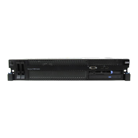
Rear View of File Module
Chapter 2. Performing the Hardware Installation
Step 5. Installing the Support Rails for Control Enclosure
Hole Locations in the Front of the Rack
Hole Locations in the Back of the Rack
Step 6. Installing the Enclosures
Removing the Enclosure End Cap
Step 7. Installing the Support Rails for File Module Slides
Securing an Enclosure to a Rack Cabinet
Cable Management Arm Box Contents
Friction Rail Box Contents
Locate a 2U Space in the Lower Section of the
Open the Rear Slide Rail Hooks
Install the Rear End of the Slide Rails
Step 8. Installing the File Modules
Install the Front End of the Slide Rails
Install the File Module on the Slide Rails
Slide the File Module into the Rack
Install the Cable Management Support Arm. the Graphic Shows the Rear of the Rack
Install the Cable Management Arm
Adjust the Location of the Cable Management Arm
Connect and Route the Cables
Step 9. Connecting the SAS Cables to the Expansion Enclosures
Secure the Cable Management Arm and the File Module in the Rack for Shipping if Needed
Install the Front Screws
How to Connect SAS Cables to Expansion Units
Internal Cables. this Is a Logical Diagram of the Connectivity and Does Not Reflect the Exact Physical System
Enclosure
Attaching an Expansion Enclosure to the Control Enclosure
Adding a Second Expansion Enclosure
Step 10. Attaching the Ethernet Cables
Attaching SAS Cables to the Enclosures
Control Enclosure Ethernet Network Connections. this Diagram Is Conceptual, Not a Physical Representation
File Module Node Ethernet Network Connections. this Is a Logical Diagram of the Connectivity and Does Not Reflect the Exact Physical System
Ethernet Connections Available with the Control Enclosure
Ethernet Connections Available with the File
Step 11. Attaching the Fibre Channel Cables
Diagram Showing How to Connect the File Modules to the Control Enclosure Using Fibre Channel Cables. Refer to Previous Table
How to Connect Fibre Channel Cables from File Modules to the Controller. Refer to the Graphic below
Step 12. Connecting the Power Cords
Step 13. Powering the System on and off
Sliding the Cable Retention Bracket Directly Behind the Power Cord
Drives and Two End Caps
LED Status Front of Control Enclosure. Refers to
Leds on the Power Supply Units of the Expansion Enclosure
LED Status Rear of Control Enclosure
Leds on the Power Supply Units of the Control
LED Status When Control Enclosure Is Powered
Chapter 3. Configuring the System
Initialize the Storwize V7000
This Table (Optional) Is Useful for Identifying
Initialization Tool Welcome Panel
Create Two Files and Enter One Line Each, Adjusted to the Values Fitting to Your Environment
Initialize the File Modules
Enclosure
Modules
Configure the Software
This Table (Optional) Is Useful for Completing
Remote Support Information
CIDR Subnet Mask Information
Authentication Method Information
Active Directory Configuration Information
Ldap Configuration Information
NIS Configuration Information
Change Default Passwords
Check the Storwize V7000 Unified System Status
Upgrade the Storwize V7000 Unified Software
Problems with Initial Configuration
Enable IBM Tivoli Assist On-Site (AOS)
Appendix. Accessibility
Notices
Trademarks
Electronic Emission Notices
Federal Communications Commission (FCC) Statement
Industry Canada Compliance Statement
Avis de Conformité à la Réglementation D'industrie Canada
Australia and New Zealand Class a Statement
European Union Electromagnetic Compatibility Directive
Germany Electromagnetic Compatibility Directive
Japan VCCI Council Class a Statement
People's Republic of China Class a Electronic Emission Statement
International Electrotechnical Commission (IEC) Statement
United Kingdom Telecommunications Requirements
Korean Communications Commission (KCC) Class a Statement
Russia Electromagnetic Interference (EMI) Class a Statement
Taiwan Class a Compliance Statement
European Contact Information
Taiwan Contact Information
Advertisement
Quick Links
Download this manual
IBM Storwize V7000 Unified
Version 1.3.0
Machine Types 2073-700 and 2076
Quick Installation Guide
GA32-1056-01
Table of
Contents
Previous
Page
Next
Page
1
2
3
4
5
Advertisement
Table of Contents
Need help?
Do you have a question about the 2073-700 and is the answer not in the manual?
Ask a question
Questions and answers
Related Manuals for IBM 2073-700
Storage IBM V7000 Introduction And Implementation Manual
Flex system storage node (670 pages)
Storage IBM Storwize V7000 Unified Problem Determination Manual
(474 pages)
Storage IBM Storwize V7000 Unified Problem Determination Manual
(348 pages)
Storage IBM Storwize V7000 Unified Series Problem Determination Manual
(314 pages)
Storage IBM Storwize V7000 Troubleshooting And Maintenance Manual
(189 pages)
Storage IBM Storwize V7000 Maintenance Manual
(172 pages)
Storage IBM Storwize V7000 Unified Manual
Adding storwize v7000 file modules (153 pages)
Disk array system IBM Storwize V5100 MTM 2078-424 Quick Installation Manual
(144 pages)
Storage IBM Storwize V7000 Troubleshooting And Maintenance Manual
(142 pages)
Storage IBM Storwize V7000 Unified Quick Installation Manual
(108 pages)
Storage IBM Storwize V7000 Unified Quick Installation Manual
(102 pages)
Network Storage Server IBM Storwize V7000 Quick Installation Manual
(90 pages)
Storage IBM Storwize V7000 Quick Installation Manual
(50 pages)
Enclosure IBM Storwize V7000 Installation Manual
Expansion enclosure (45 pages)
Storage IBM Storwize V7000 Quick Reference Manual
Virtualized storage systems (2 pages)
Network Storage Server IBM xSeries 220 Hardware Maintenance Manual
(178 pages)
This manual is also suitable for:
Storwize v7000 unified
2076
Table of Contents
Print
Rename the bookmark
Delete bookmark?
Delete from my manuals?
Login
Sign In
OR
Sign in with Facebook
Sign in with Google
Upload manual
Upload from disk
Upload from URL


Need help?
Do you have a question about the 2073-700 and is the answer not in the manual?
Questions and answers