Table of Contents
Advertisement
Quick Links
Expr ess
COOK
WATT
Gr ill Ho t
CAUTION, MICROWAVE RADIATION ........................................................................ Indside front cover
SERVICING ............................................................................................................................................. 2
PRODUCT SPECIFICATIONS ................................................................................................................. 5
GENERAL INFORMATION ....................................................................................................................... 5
APPEARANCE VIEW .............................................................................................................................. 6
OPERATION SEQUENCE ........................................................................................................................ 7
FUNCTION OF IMPORTANT COMPONENTS ..................................................................................... 10
TROUBLESHOOTING GUIDE ............................................................................................................... 12
TEST PROCEDURE .............................................................................................................................. 14
CONTROL PANEL ASSEMBLY ............................................................................................................ 21
COMPONENT REPLACEMENT AND ADJUSTMENT PROCEDURE .................................................. 26
MICROWAVE MEASUREMENT ........................................................................................................... 32
TEST DATA AT A GLANCE .................................................................................................................. 32
WIRING DIAGRAM ................................................................................................................................ 33
PICTORIAL DIAGRAM .......................................................................................................................... 37
POWER UNIT CIRCUIT ......................................................................................................................... 38
CPU UNIT CIRCUIT ............................................................................................................................... 39
INDICATOR CIRCUIT ............................................................................................................................. 40
JOG AND SWITCH CIRCUIT ................................................................................................................. 41
PRINTED WIRING BOARD OF POWER UNIT ...................................................................................... 42
PRINTED WIRING BOARD OF JOG AND SWITCH UNIT .................................................................... 43
PARTS LIST .......................................................................................................................................... 44
SERVICE MANUAL
D
NL
F
I
E
MODELS
AUTO
REHEAT
Expr ess
AUTO
DEFROS T
COOK
˚C
/KG
STOP
+
1
min
R-933
Ai r
In interests of user-safety the oven should be restored to its original
condition and only parts identical to those specified should be used.
TABLE OF CONTENTS
SHARP CORPORATION
MICROWAVE OVEN WITH
GRILL AND CONVECTION
R-933(IN)
R-933(W)
S07283R933EHW
Page
Advertisement
Table of Contents

Related Manuals for Sharp R-933


Summary of Contents for Sharp R-933
-
Page 1: Table Of Contents
SERVICE MANUAL S07283R933EHW MICROWAVE OVEN WITH GRILL AND CONVECTION R-933(IN) MODELS AUTO REHEAT Expr ess Expr ess COOK AUTO DEFROS T COOK WATT ˚C R-933(W) STOP R-933 Gr ill Ho t Ai r In interests of user-safety the oven should be restored to its original condition and only parts identical to those specified should be used. - Page 2 CAUTION MICROWAVE RADIATION Personnel should not be exposed to the microwave energy which may radiate from the magnetron or other microwave generating devices if it is improperly used or connected. All input and output microwave connections, waveguides, flanges and gaskets must be secured.
-
Page 3: Caution, Microwave Radiation
GRILL AND CONVECTION MICROWAVE OVEN R-933(IN)/ R-933(W) GENERAL INFORMATION GENERAL IMPORTANT INFORMATION This Manual has been prepared to provide Sharp Corp. Service engineers with Operation and Service Information. APPEARANCE VIEW It is recommended that service engineers carefully study the entire text of this manual, so they will be qualified to render satisfactory customer service. -
Page 4: Servicing
Sharp beveelt ten sterkste aan dat, voor zover mogelijk, defecten worden opgespoord wanneer de stekker uit het Wanneer alle reparaties zijn uitgevoerd en de oven weer in stopcontact is gehaald. - Page 5 är kallt utför Du 3 steg kontroller och kontrollerar anslutningarna till varje enskild komponent på nytt. Sharp rekommenderar att felsökning sker med strömmen fränkopplad. Ibland kan det var nödvändigt att koppla på När all service är klar och ugnen ihopskruvad skall ugnens strömmen efter det att höljet avlägsnats, utför da 3 Steg...
- Page 6 Sharp raccomanda, nei limiti del possibile, che la ricerca dei guasti avvenga in assenza di alimentazione elettrica. Dopo aver portato a termine le operazioni di manutenzione In alcuni casi tuttavia, può...
-
Page 7: Product Specifications
PRODUCT DESCRIPTION SPECIFICATION ITEM DESCRIPTION Power Requirements 230 Volts / 50 Hertz / Single phase, 3 wire earthed Power Consumption Microwave cooking 1.5 kW Approx. 6.7 A Convection cooking 2.65 kW Approx. 11.5 A Grill cooking 2.65 kW Approx. 11.5 A Micro and Grill ...... -
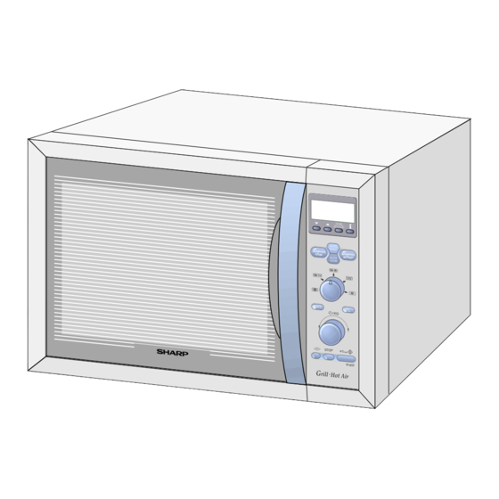
Page 8: Appearance View
STOP button is pressed. STOP 15. STOP button 16. CLOCK SETTING button R-933 17. MICROWAVE POWER LEVEL button Press to change the microwave power setting. Grill . Hot Air 18. EXPRESS COOK button 19. LESS / MORE buttons... -
Page 9: Operation Sequence
OPERATION SEQUENCE OFF CONDITION transformer, fan motor and turntable motor are cut off. 5. When the oven door is opened during a cooking cycle, Closing the door activates the monitored latch switch and the switches come to the following condition. the stop switch. - Page 10 OPERATION SEQUENCE WEIGHT dial. And select the desired cooking tempera- Note: The On/Off time ratio does not exactly correspond ture 250˚C by pressing the CONVECTION button. When to the percentage of microwave power, because the START button is pressed, the following operations approx.
- Page 11 OPERATION SEQUENCE FAN MOTOR OPERATION (in Grill, Convection down to zero. and Dual mode) 2. The oven lamp, fan motor and turntable motor are energized. When oven is stopped during cooking, or after the cooking 3. The relay RY3 is energized and the main supply is completed, the fan motor will operate if the oven cavity voltage is applied to the grill heating elements.
-
Page 12: Function Of Important Components
FUNCTION OF IMPORTANT COMPONENTS DOOR OPEN MECHANISM CAUTION: BEFORE REPLACING A BLOWN FUSE F2 F8A, TEST THE MONITORED LATCH The door can be opened by puiiing the door handle. SWITCH SW1 AND MONITOR SWITCH When the door handle is pulled, the latch head is moved SW3 FOR PROPER OPERATION. - Page 13 FUNCTION OF IMPORTANT COMPONENTS CONVECTION COOKING SYSTEM ASYMMETRIC RECTIFIER This oven is designed with a hot air heating system where The asymmetric rectifier is solid state device that prevents food is heated by forced circulation of the hot air produced current flow in both directions.
-
Page 14: Troubleshooting Guide
OPERATION SEQUENCE 32 (sec.) THERMISTOR 1-3. When the damper is moved to the open position by the damper cam, damper switch SW4 is closed (ON Sensing position). Voltage 1-4. The signal of damper switch SW4 is re-sensed in the Sensing the voltage across temperature measurement circuit. control unit and shut-off relay (RY8) is turned off. - Page 15 TROUBLESHOOTING GUIDE BLOCKED COOLING FAN BLOCKED CONVECTION FAN NO POWER AT WALL OUTLET HOME FUSE OR BREAKER MIS-ADJUSTMENT OF SWITCHES BLOCKED VENTILATION OPENINGS OPENED WIRE HARNESS SHORTED WIRE HARNESS OVEN LAMP OR SOCKET POWER SUPPLY CORD FOIL PATTERN ON P.W.B. RELAY RY8 RELAY RY7 RELAY RY6...
-
Page 16: Test Procedure
TEST PROCEDURES PROCEDURE COMPONENT TEST LETTER MAGNETRON TEST NEVER TOUCH ANY PART IN THE CIRCUIT WITH YOUR HAND OR AN INSULATED TOOL WHILE THE OVEN IS IN OPERATION. CARRY OUT 3D CHECKS. Isolate the magnetron from high voltage circuit by removing all leads connected to filament terminal. To test for an open circuit filament use an ohmmeter to make a continuity test between the magnetron filament terminals, the meter should show a reading of less than 1 ohm. - Page 17 TEST PROCEDURES PROCEDURE COMPONENT TEST LETTER Room temperature ....... To = 21˚C Initial temperature ..... T1 = 11°C Temperature after (47 + 3) = 50 sec..............T2 = 21°C Temperature difference Cold-Warm ..............∆T1 = 10°C Measured output power The equation is “P = 90 x ∆T”...
- Page 18 TEST PROCEDURES PROCEDURE COMPONENT TEST LETTER THE MEASURING INSTRUMENT MUST HAVE A VOLTAGE AT LEAST 6 VOLTS, BE- CAUSE OTHERWISE AN INFINITE RESISTANCE MIGHT BE SHOWN IN BOTH DIREC- TIONS. HIGH VOLTAGE CAPACITOR TEST CARRY OUT 3D CHECKS. A. Isolate the high voltage capacitor from the circuit. B.
- Page 19 TEST PROCEDURES PROCEDURE COMPONENT TEST LETTER An open circuit thermal cut-out (MG) TC1 indicates that the magnetron has overheated, this may be due to resistricted ventilation, cooling fan failure. An open circuit thermal cut-out (GRILL) TC2 indicates that the oven cavity has overheated, this may be due to no load operation..
- Page 20 TEST PROCEDURES PROCEDURE COMPONENT TEST LETTER 3. If the fuse F2 F8A is blown, there could be shorts in the asymmetric rectifier or there is a ground in wire harness. A short in the asymmetric rectifier may be occurred due to short or ground in H.V. rectifier, magnetron, high voltage transformer or H.V.
- Page 21 TEST PROCEDURES PROCEDURE COMPONENT TEST LETTER 2-3 Other possible troubles caused by defective control unit. a) Buzzer does not sound or continues to sound. b) Clock does not operate properly. c) Cooking is not possible. d) Proper temperature measurement is not obtained. JOG AND SWITCH UNIT TEST If the display fails to clear when the STOP button J-13...
- Page 22 TEST PROCEDURES PROCEDURE COMPONENT TEST LETTER PROCEDURES TO BE TAKEN WHEN THE FOIL PATTERN ON THE PRINTED WIRING BOARD (PWB) IS OPEN To protect the electronic circuits, this model is provided with a fine foil pattern added to the input circuit on the PWB, this foil pattern acts as a fuse.
-
Page 23: Control Panel Assembly
CONTROL PANEL ASSEMBLY OUTLINE OF CONTROL PANEL The control section consists of the following units as 3) Synchronizing Signal Circuit shown in the control panel circuit. The power source synchronizing signal is available in order to compose a basic standard time in the clock circuit. - Page 24 DESCRIPTION OF LSI LSI(IXA036DR) The I/O signal of the LSI(IXA036DR) are detailed in the following table. Pin No. Signal Description Terminal not used. Timing signal output terminal for temperature measurement(OVEN THERMISTOR). "H" level (GND) : Thermistor OPEN timing. "L" level (-5V) : Temperature measuring timing. (Convection cooking) Timing signal output terminal for temperature measurement(OVEN THERMISTOR).
- Page 25 DESCRIPTION OF LSI Pin No. Signal Description INT0 Signal to synchronized LSI with commercial power source frequency(50Hz). This is basic timing for time processing H : GND of LSI. L (-5V) 20 msec. CNVSS Connected to VC. RESET Auto clear terminal. Signal is input to reset the LSI to the initial state when power is applied.
- Page 26 DESCRIPTION OF LSI Pin No. Signal Description Damper motor relay driving signal. To turn on and off shut-off relay (RY8). Touch control transformer driving signal. To turn on and off the shut off relay (RY5). If the oven has not been used for more than 2 minutes, the relay RY5 will be turned off.
- Page 27 SERVICING 1. Precautions for Handling Electronic Components 5) Re-connect the power supply cord after the outer This unit uses CMOS LSI in the integral part of the circuits. case is installed. When handling these parts, the following precautions 6) Run the oven and check all functions. should be strictly followed.
-
Page 28: Component Replacement And Adjustment Procedure
Oven lamp, Magnetron, High voltage trans- To prevent an electric shock, take the following former and Oven cavity. manners. 3) Sharp edge: 1. Before wiring, Bottom plate, Oven cavity, Weveguide flange, 1) Disconnect the power supply. Chassis support and other metallic plate. - Page 29 COMPONENT REPLACEMENT AND ADJUSTMENT PROCEDURE HIGH VOLTAGE TRANSFORMER REMOVAL 1. CARRY OUT 3D CHECKS. 4. Remove the two (2) screws and one (1) washer holding 2. Disconnect the main wire harness from the high volt- the transformer to the base plate. age transformer.
- Page 30 4. Cut the three (3) bridges holding the turntable motor Re-install 1. Remove the any sharp edges on the turntable motor cover to the base plate with cutting pliers as shown in cover and the base plate with the cutting pliers.
- Page 31 COMPONENT REPLACEMENT AND ADJUSTMENT PROCEDURE 17. Remove the one (1) screw holding the convection 16. Remove the convection fan from the convection motor heater angle and the air separate angle D to the shaft. convection duct. 17. Remove the pipe from the convection motor shaft. 18.
- Page 32 COMPONENT REPLACEMENT AND ADJUSTMENT PROCEDURE GRILL HEATING ELEMENTS REMOVAL 1. CARRY OUT 3D CHECKS. the oven cavity top plate, slide the grill reflector toward 2. Disconnect wire leads from the thermal cut-out (GRILL). the magnetron. And then lift up the grill reflector and 3.
- Page 33 COMPONENT REPLACEMENT AND ADJUSTMENT PROCEDURE DOOR REPLACEMENT to door frame. REMOVAL 4. Re-install door panel to door frame. 1. Disconnect the oven from the power supply. 5. Hold the door panel to the door frame with six (6) 2. Push the door slightly. screws.
-
Page 34: Microwave Measurement
MICROWAVE MEASUREMENT Recommended instruments are: After adjustment of door latch switches, monitor switch NARDA 8100 and door are completed individually or collectively, the NARDA 8200 following leakage test must be performed with a survey HOLADAY HI 1500 instrument and it must be confirmed that the result meets SIMPSON 380M the requirements of the performance standard for micro- 2. -
Page 35: Wiring Diagram
SCHEMATICS Note: SCHEMATIC AC CORD CONNECTION NOTE: CONDITION OF OVEN BRN : BROWN 1. DOOR CLOSED. BLU : BLUE 2. PLUGGED IN OVEN. G-Y : GREEN AND YELLOW STRIPE 3. NOTHING APPEARS ON DISPLAY. /15 : SECTIONAL AREA OF 1.5mm MIN. - Page 36 SCHEMATICS Note: SCHEMATIC AC CORD CONNECTION NOTE: CONDITION OF OVEN BRN : BROWN 1. DOOR CLOSED. BLU : BLUE 3. " . O" APPEARS ON DISPLAY. G-Y : GREEN AND YELLOW STRIPE /15 : SECTIONAL AREA OF 1.5mm MIN. " "...
- Page 37 SCHEMATICS SCHEMATIC NOTE: CONDITION OF OVEN 1. DOOR CLOSED. 2. GRILL MODE SET. NOTE: The convection cooking will be curried out as back up until the 3. COOKING TIME SET. oven cavity temperature rises to 220 ˚C 4. STRAT BUTTON PRESSED. CONTROL UNIT SW4:...
- Page 38 SCHEMATICS Note: SCHEMATIC NOTE: CONDITION OF OVEN AC CORD CONNECTION 1. DOOR CLOSED. BRN : BROWN 2. DUAL 1 MODE SET. BLU : BLUE 3. COOKING TIME SET. G-Y : GREEN AND YELLOW STRIPE 4. MICROWAVE POWER LEVEL SET. /15 : SECTIONAL AREA OF 1.5mm MIN.
-
Page 39: Pictorial Diagram
PICTORIAL DIAGRAM... -
Page 40: Power Unit Circuit
POWER UNIT CIRCUIT OVEN S1NB10 WH1-4 THERMISTOR WH1-3 – – R4 510 1w WH1-6 Q1 2SB1238 R5 3.3k WH1-9 BUZZER AC230V R3 680 1w 50Hz WH2-2 WH1-10 WH1-5 POWER WH1-11 CONTROL FAN MOTOR WH1-8 CONVECTION WH1-7 MOTOR DAMPER WH2-4 MOTOR R6 130 1w OVEN LAMP WH2-3... -
Page 41: Cpu Unit Circuit
CPU UNIT CIRCUIT... -
Page 42: Indicator Circuit
INDICATOR CIRCUIT... -
Page 43: Jog And Switch Circuit
JOG AND SWITCH UNIT CIRCUIT : IF NOT SPECIFIED 0.01µF / 25V : IF NOT SPECIFIED 1/10W ± 5% J - 6 J - 5 J - 2 J - 1 CN - J AUTO IC1-6(P73) COOK R68 15 k IC1-7(P72) WATT R69 15 k... -
Page 44: Printed Wiring Board Of Power Unit
PRINTED WIRING BOARD OF POWER UNIT VRS1 POWER CONT Figure S-6. Printed Wiring Board of Power Unit... -
Page 45: Printed Wiring Board Of Jog And Switch Unit
PRINTED WIRING BOARD OF JOG AND SWITCH UNIT SW11 DUCT SW10 SW12 SW13 Figure S-7. Printed Wiring Board of Jog and Switch Unit... -
Page 46: Parts List
RTRN-A529WRE0 TC transformer 1- 5 FH-HZA075WRE0 Thermistor CABINET PARTS 2- 1 GCABDA005URP0 Back plate 2- 2 GCABUA038URP0 Outer case cabinet [R-933(IN)] 2- 2 GCABUA037URP0 Outer case cabinet [R-933(W)] 2- 3 GLEGPA028WRE0 Foot 2- 4 GDAI-A003URP0 Base plate CONTROL PANEL PARTS... - Page 47 Timer knob [R-933(IN)] 3- 12 JKNBKR008URF0 Timer knob [R-933(W)] 3- 13 MSPR-A006WREZ Switch spring 3- 14 HPNLCS016URT0 Control panel frame [R-933(IN)] 3- 14 HPNLCW052URF0 Control panel frame [R-933(W)] 3- 15 XEPSD30P10XS0 Screw : 3mm x 10mm OVEN PARTS 4- 1...
- Page 48 " may cause undue microwave exposure. / The parts marked "*" are used in voltage more than 250V. / "§" Mark: Spare parts delivery section REF. NO. PART NO. § DESCRIPTION Q'TY CODE 5-1-4 JHNDPK001URF0 Door handle [R-933(IN)] 5-1-4 JHNDPS001URT0 Door handle [R-933(W)] 5-1-5 LSTPPA017URF0 Latch head 5-1-6 MSPRTA197WREZ...
- Page 49 EXPLODED VIEW OF OVEN OVEN PARTS 7-16 4-17 7-10 4-25 6-11 7-13 4-18 4-20 7-17 4-39 4-27 7-16 4-10 4-22 7-16 4-21 4-19 4-13 7-13 7-13 4-23 4-15 7-17 7-12 7-16 4-16 7-10 7-18 4-24 4-14 4-11 7-16 7-14 4-26 7-12 4-30 4-29...
- Page 50 CONTROL PANEL AND DOOR PARTS CONTROL PANEL PARTS 3-15 3-15 3-15 3-13 3-14 3-12 3-11 DOOR PARTS 3-10 5-1-8 5-1-1 5-1-2 5-1-3 5-1-8 5-1-5 5-1-7 5-1-6 5-1-4...
- Page 51 TOP PAD ASSEMBLY (FPADBA303WRK2) LOW RACK WRAP COVER (SSAKHA041WRE0) HIGH RACK DOOR PROTECTION SHEET ROLLER STAY ASSEMBLY (SPADPA020WRE0) PRINTED MATTER BOTTOM PAD ASSEMBLY (FPADBA304WRK3) ACCESSORY HOLDER INTO THE (SPADPA019URE0) OVEN CAVITY PACKING CASE R-933(W); SPAKCA379URR0 R-933(IN); SPAKCA380URR0 Not Replaceable Items.
- Page 52 No part of this publication may be reproduced, stored in a retrieval system, or transmitted in any form or by any means, electronic, mechanical, photocopying, recording, or otherwise, without prior written permission of the publisher. 2000 SHARP CORP. (7S1.31E) Printed in U.K.
Need help?
Do you have a question about the R-933 and is the answer not in the manual?
Questions and answers