Table of Contents
Advertisement
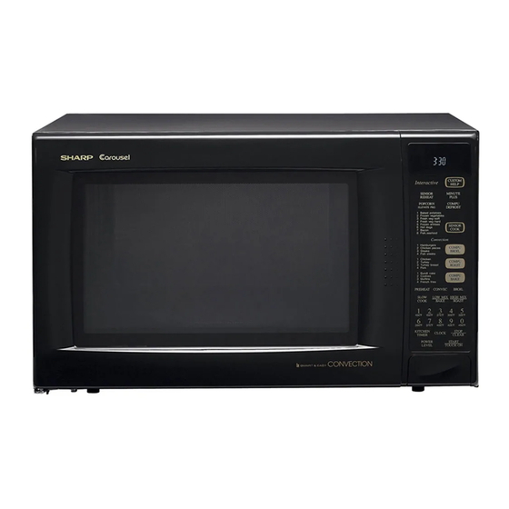
R-930AW
BEFORE SERVICING ........................................................................................................................................... 1
MICROWAVE MEASUREMENT PROCEDURE ................................................................................................... 2
FOREWORD .......................................................................................................................................................... 3
PRODUCT SPECIFICATIONS .............................................................................................................................. 4
GENERAL INFORMATION ................................................................................................................................... 4
OPERATION .......................................................................................................................................................... 6
TROUBLESHOOTING GUIDE ............................................................................................................................ 13
TEST PROCEDURE ............................................................................................................................................ 14
TOUCH CONTROL PANEL ................................................................................................................................. 21
COMPONENT REPLACEMENT AND ADJUSTMENT PROCEDURE ................................................................ 27
PICTORIAL DIAGRAM ........................................................................................................................................ 33
CONTROL PANEL CIRCUIT ............................................................................................................................... 34
PRINTED WIRING BOARD ................................................................................................................................. 35
PARTS LIST ........................................................................................................................................................ 36
PACKING AND ACCESSORIES ......................................................................................................................... 39
SHARP ELECTRONICS CORPORATION
Service Headquarters:
SERVICE MANUAL
MIX CONV
DEFROST
SENSOR
COOK LBS
OZ
KG
HELP
Interac tive
CUSTOM
HELP
SENSOR
MINUTE
REHEAT
PLUS
POPCORN
COMPU
ELEVATE PKG
DEFROST
1 Baked potatoes
2 Frozen vegetables
3 Fresh veg-soft
4 Fresh veg-hard
5 Frozen entrees
6 Hot dogs
SENSOR
7 Bacon
COOKT
8 Fish, seafood
Convecti on
1 Hamburge rs
2 Chicken pieces
COMPU
3 Steaks
BROIL
4 Fish steaks
1 Chicken
MODELS
2 Turkey
COMPU
3 Turkey breast
4 Pork
ROAST
1 Bundt cake
2 Cookies
COMPU
3 Muffins
4 French fries
BAKE
PREHEAT
CONVEC
BROIL
SLOW
LOW MIX
HIGH MIX
COOK
BAKE
ROAST
1
2
3
4
5
100˚F
150˚F
275˚F
300˚F
6
325˚F
7
8
9
0
350˚F
375˚F
400˚F
425˚F
150˚F
KITCH EN
TIMER
CLOCK
ST OP
TCLEA R
POWER
START
LEVEL
TOUCH ON
In the interest of user-safety the oven should be restored to its original
condition and only parts identical to those specified should be used.
TABLE OF CONTENTS
Sharp Plaza,
CONVECTION
MICROWAVE OVEN
R-930AK
R-930AW
Mahwah,
New Jersey
R-930AK
R-930AW
S6710R930APW/
Page
07430-2135
Advertisement
Table of Contents

Related Manuals for Sharp R930AK - 1.5 CF 900 Watts Convection Sensor Interactive; Charcoal


Summary of Contents for Sharp R930AK - 1.5 CF 900 Watts Convection Sensor Interactive; Charcoal
-
Page 1: Table Of Contents
COMPONENT REPLACEMENT AND ADJUSTMENT PROCEDURE ..............27 PICTORIAL DIAGRAM ............................33 CONTROL PANEL CIRCUIT ..........................34 PRINTED WIRING BOARD ..........................35 PARTS LIST ................................ 36 PACKING AND ACCESSORIES ......................... 39 SHARP ELECTRONICS CORPORATION Service Headquarters: Sharp Plaza, Mahwah, New Jersey 07430-2135... -
Page 2: Precautions To Be Observed Before And During Service To Avoid Possible Exposure To Excessive Microwave Energy
R-930AK R-930AW PRECAUTIONS TO BE OBSERVED BEFORE AND DURING SERVICING TO AVOID POSSIBLE EXPOSURE TO EXCESSIVE MICROWAVE ENERGY (a) Do not operate or allow the oven to be operated with the door open. (b) Make the following safety checks on all ovens to be serviced before activating the magnetron or other microwave source, and make repairs as necessary: (1) interlock operation, (2) proper door closing, (3) seal and sealing surfaces (arcing, wear, and other damage), (4) damage to or loosening of hinges and latches, (5) evidence of dropping or abuse. -
Page 3: Before Servicing
Before servicing an operative unit, perform a microwave emission check as per the Microwave Measurement Procedure outlined in this service manual. If microwave emissions level is in excess of the specified limit, contact SHARP ELECTRONICS CORPORATION immediately 1- (800) 237-4277. -
Page 4: Microwave Measurement Procedure
R-930AK R-930AW MICROWAVE MEASUREMENT PROCEDURE A. Requirements: 1) Microwave leakage limit (Power density limit): The power density of microwave radiation emitted by a microwave oven should not exceed 1mW/cm at any point 5cm or more from the external surface of the oven, measured prior to acquisition by a purchaser, and thereafter (through the useful life of the oven), 5 mW/cm at any point 5cm or more from the external surface of the oven. -
Page 5: Foreword
CONVECTION MICROWAVE OVEN GENERAL INFORMATION R-930AK / R-930AW FOREWORD This Manual has been prepared to provide Sharp Electronics OPERATION Corp. Service Personnel with Operation and Service Informa- tion for the SHARP CONVECTION MICROWAVE OVENS R- 930AK / R-930AW. TROUBLESHOOTING GUIDE... -
Page 6: Product Specifications
R-930AK R-930AW SPECIFICATION ITEM DESCRIPTION Power Requirements 120 Volts 13.0 Amperes (Microwave) / 13.0 Amperes (Convection) 60 Hertz / Single phase, 3 wire grounded Power Output 900 watts (IEC 705 Test Procedure) Operating frequency of 2450MHz Convection Power Output 1450 Watts Case Dimensions Width 24-5/8"... -
Page 7: Oven Diagram
R-930AK R-930AW Electrical Requirements The electrical requirements are a 115 -120 volt 60 Hz, AC only, Grounded 3-Pronged Plug Receptacle Box 15 or 20 amp. fused electrical supply. It is recommended that a separate circuit serving only this appliance be provided. When installing this appliance, observe all applicable codes and ordinances. -
Page 8: Operation
(Figure O-1). (1) When the door opens from a closed position, the primary 1. The display will show "SHARP SIMPLY THE BEST interlock relay and the secondary interlock switch open PRESS CLEAR AND PRESS CLOCK". - Page 9 R-930AK R-930AW first. And then program desired cooking time by touching the CONVECTION COOKING CONDITION Number pads. The LOW MIX/BAKE pad is preprogrammed PREHEATING CONDITION for 350˚F with 10% microwave power, while the HIGH MIX/ Program desired convection temperature by touching the ROAST pad is preprogrammed for 300˚F with 30% micro- CONVECTION pad and the Temperature pad.
- Page 10 R-930AK R-930AW The sensor “senses” the vapor and its resistance increases 4. Now, the oven is in the convection cooking mode. gradually. When the resistance reaches the value set ac- 5. When the oven temperature has reached the programmed cording to the menu, supplementary cooking is started. convection temperature, the oven goes into the The time of supplementary cooking is determined by experi- programmed cooking mode.
-
Page 11: Schematic Diagram
R-930AK R-930AW IMPORTANT: detected vapors and initiated a sensor cooking cycle. During sensor cooking operation, the fire sensing op- This is because the operation of the convection fan eration sequence will not begin until the AH sensor has would interfere with the AH sensor's vapor detection. SCHEMATIC DIAGRAM SCHEMATIC NOTE: CONDITION OF OVEN... - Page 12 R-930AK R-930AW SCHEMATIC 1. DOOR CLOSED. 2. MIX COOKING PAD TOUCHED. 3. COOKING TIME PROGRAMMED. 4. “START” PAD TOUCHED. 5. RY2 AND RY3 WILL ALTERNATELY CLOSE. DURING COOK CYCLE. CONV. MAGNETRON TEMPERATURE THERMAL FUSE CUT-OUT FUSE COM. POWER (RY1) TRANSFORMER N.O.
- Page 13 R-930AK R-930AW DESCRIPTION AND FUNCTION OF COMPONENTS DOOR SENSING AND SECONDARY INTERLOCK OUTER CASE SWITCHES SWITCHES The two outer case switches are mounted near the power The door sensing switch in the primary interlock system is supply cord at the oven cavity rear plate. When the outer mounted in the upper position on the latch hook, the case cabinet is installed with the screws, one of the screws secondary interlock switch is mounted in the lower position...
-
Page 14: Troubleshooting Guide
R-930AK R-930AW HEATING ELEMENT Damper is in the closed position, so that no hot air will be allowed to leak out the oven cavity. The heating element is located at the left side of the oven cavity. It is intended to heat air driven by the convection fan. Damper Operation The heated air is kept in the oven and force-circulated and 1. - Page 15 R-930AK R-930AW (SENSOR CONDITION COOKING CONDITION OFF CONDITION (MICROWAVE) (CONVECTION) COOKING) POSSIBLE CAUSE DEFECTIVE PARTS MAGNETRON POWER TRANSFORMER H.V. RECTIFIER ASSEMBLY HIGH VOLTAGE CAPACITOR SECONDARY INTERLOCK SWITCH PRIMARY INTERLOCK SYSTEM MONITOR SWITCH MONITOR FUSE MAGNETRON TEMPERATURE FUSE CONV. THERMAL CUT-OUT CONVECTION HEATER THERMISTOR DAMPER MOTOR...
-
Page 16: Test Procedure
R-930AK R-930AW TEST PROCEDURES PROCEDURE COMPONENT TEST LETTER MAGNETRON ASSEMBLY TEST HIGH VOLTAGES ARE PRESENT DURING THE COOK CYCLE, SO EXTREME CAUTION SHOULD BE OBSERVED. DISCHARGE THE HIGH VOLTAGE CAPACITOR BEFORE TOUCHING ANY OVEN COMPONENTS OR WIRING. To test for an open filament, isolate the magnetron from the high voltage circuit. A continuity check across the magnetron filament leads should indicate less than 1 ohm. - Page 17 R-930AK R-930AW TEST PROCEDURES PROCEDURE COMPONENT TEST LETTER If the capacitor is open, no high voltage will be available to the magnetron. Disconnect input leads and check for short or open between the terminals using an ohmmeter. Checking with a high ohm scale, if the high voltage capacitor is normal, the meter will indicate continuity for a short time and should indicate approximately 10 M once the capacitor is charged.
- Page 18 R-930AK R-930AW TEST PROCEDURES PROCEDURE COMPONENT TEST LETTER An open temperature fuse indicates overheating of the magnetron assembly, check for restricted air flow to the magnetron through the opening in the chassis, especially the cooling duct and cooling fan. THERMAL CUT-OUT TEST A continuity check across the thermal cut-out terminals should indicate a closed circuit unless the temperature of thermal cut-out reaches 302˚F(150˚C).
- Page 19 R-930AK R-930AW TEST PROCEDURES PROCEDURE COMPONENT TEST LETTER temperature is reached (audible signal sounds four times). The temperature experienced may be approx. 30˚F more or less than indicated on the display, however, in most cases the food cooking results will be satisfactory. Difference in power supply voltage will also affect the oven temperature.
- Page 20 R-930AK R-930AW TEST PROCEDURES PROCEDURE COMPONENT TEST LETTER If the control unit responds by clearing with a beep the key unit is faulty and must be replaced. If the control unit does not respond, it is a faulty and must be replaced. If a specific pad does not respond, the above method may be used (after clearing the control unit) to determine if the control unit or key pad is at fault.
- Page 21 R-930AK R-930AW TEST PROCEDURES PROCEDURE COMPONENT TEST LETTER Problem: POWER ON, indicator does not light up. STEPS OCCURRENCE CAUSE OR CORRECTION The rated voltage is not applied to POWER Check supply voltage and oven power cord. terminal of CPU connector (CN-A). The rated voltage is applied to primary side Power transformer or secondary circuit defective.
- Page 22 R-930AK R-930AW TEST PROCEDURES PROCEDURE COMPONENT TEST LETTER NOTE: ERROR will appear if the door is opened or STOP/CLEAR pad is touched during first stage of sensor cooking. (6) After approximately 16 seconds, microwave energy is produced, and the display should start to count down the remaining cooking time and oven should turn off after water is boiling (bubbling).
-
Page 23: Touch Control Panel
R-930AK R-930AW TOUCH CONTROL PANEL ASSEMBLY OUTLINE OF TOUCH CONTROL PANEL The touch control section consists of the following units 4) ACL Circuit as shown in the touch control panel circuit. A circuit to generate a signals which resetting the LSI to the initial state when power is applied. - Page 24 R-930AK R-930AW DESCRIPTION OF LSI LSI(IZA797DR): The I/O signals of the LSI(IZA797DR) are detailed in the following table. Pin No. Signal Description Connected to GND. Anode (segment) of Fluorescent Display light-up voltage: -30V. Vp voltage of power source circuit input. AVSS Power source voltage: -5V.
- Page 25 R-930AK R-930AW Pin No. Signal Description Magnetron high-voltage circuit driving VARI MODE ON TIME OFF TIME signal. P-HI (100% power) 32 sec. 0 sec. P-90 (approx. 90% power) 30 sec. 2 sec. To turn on and off the cook relay(RY2). In P-80 (approx.
- Page 26 R-930AK R-930AW Pin No. Signal Description Signal similar to P27. When any one of G-2 line key on key matrix is touched, a corresponding signal will be input into P26. Signal similar to P27. When any one of G-3 line key on key matrix is touched, a corresponding signal will be input into P25.
- Page 27 R-930AK R-930AW Pin No. Signal Description Segment data signal. Signal similar to P23. Key strobe signal. Signal applied to touch-key section. A pulse signal is input to P24-P27 terminal while one of G-5 line keys on key matrix is touched. 49-53 P07-P03 Segment data signal.
- Page 28 R-930AK R-930AW SERVICING 1. Precautions for Handling Electronic Components while keeping it connected to the oven. This unit uses CMOS LSI in the integral part of the B. On some models, the power supply cord between the circuits. When handling these parts, the following touch control panel and the oven proper is long enough precautions should be strictly followed.
-
Page 29: Component Replacement And Adjustment Procedure
CAUTION: DISCONNECT OVEN FROM POWER SUPPLY BEFORE REMOVING OUTER CASE. DISCHARGE HIGH VOLTAGE CAPACITOR BEFORE TOUCHING ANY OVEN COMPONENTS OR WIRING AFTER REMOVING OUTER CASE. WARNING FOR WIRING 3) Sharp edge: To prevent an electric shock, take the following man- Bottom plate, Oven cavity, Weveguide flange, ners. - Page 30 R-930AK R-930AW transformer. with two screws to the base cabinet, one is with outer 5. Disconnect wire leads from the transformer. tooth washer and the other is without outer-tooth washer. 6. Remove two (2) screws holding the transformer to the 5.
- Page 31 R-930AK R-930AW TURNTABLE MOTOR REMOVAL 1. Disconnect the oven from power supply. 3. Disconnect wire lead from the turntable motor. Remove the turntable tray, and the turntable support out 4. Remove the two (2) screws holding the turntable motor of the oven cavity. and coupling mounting plate to the oven cavity bottom.
- Page 32 R-930AK R-930AW 8. Remove the magnetron air guide from the waveguide. INSTALLATION 9. Disconnect wire leads from the fan motor. 1. Install the fan motor to the fan duct with the two (2) 10. Release the main harness from the hole of the fan duct. screws and nuts.
- Page 33 R-930AK R-930AW DOOR SENSING SWITCH/SECONDARY INTERLOCK SWITCH AND MONITOR SWITCH REMOVAL 1. Disconnect oven from power supply and remove outer At this time switch lever will be free, do not lose it. Re-install case. 1. Re-install switch lever and each interlock switch in its 2.
-
Page 34: Door Disassembly
R-930AK R-930AW Note: The door on a microwave oven is designed to act as an electronic seal preventing the leakage of UPPER OVEN HINGE microwave energy from oven cavity during cook cycle. This function does not require that door be airtight, moisture (condensation)-tight or light-tight. -
Page 35: Pictorial Diagram
R-930AK R-930AW... -
Page 36: Control Panel Circuit
R-930AK R-930AW 3.3k 3.3k 3.3k 3.3k 3.3k 3.3k 3.3k 100k 100k 100k 3.3k R100 3.3k 3.3k 3.3k 3.3k IZA797DR 4.7k 2.2kF (J7) 4.7k (J5) HZ4A2 100F (J3) /35v (J6) /50v (J4) /50v 0.01 HZ5C2 (J2) /25v 3.3k /35v /50v /50v HZ16-1 SP40 1/2w... -
Page 37: Printed Wiring Board
R-930AK R-930AW (C81) R86(J8) (C80) (R45) (C45) (CN - D) (R47) (R48) (R49) (C46) (C47) (J7) (J5) (J3) (J2) (J4) (J6) CONV HEATER COM Figure S-3. Printed Wiring Board... -
Page 38: Parts List
R-930AK R-930AW PARTS LIST Refer to "MPORTANT" described at end of parts list. REF. NO. PART NO. DESCRIPTION Q'TY CODE ELECTRICAL PARTS 1- 1 FACCDA048WRE0 Power supply cord 1- 2 FFS-BA012WRK0 Monitor fuse 20A and monitor switch (V-5220D-070) assembly 1- 3 QFSHDA009WRE0 Fuse holder 1- 4... - Page 39 R-930AK R-930AW REF. NO. PART NO. DESCRIPTION Q'TY CODE RH-IZA797DRE0 RH-IZA495DRE0 VS2SB910MR/-4 Transistor (2SB910M) VSKRA101M//-3 Transistor (KRA101M) VSDTA123ES/-3 Transistor (DTA123E) Q20-23 VSKRA101M//-3 Transistor (KRA101M) Q24-25 VSKRA223M//-3 Transistor (KRA223M) VSKRC243M//-3 Transistor (KRC243M) VSKRA101M//-3 Transistor (KRA101M) VSKRA101M//-3 Transistor (KRA101M) VRD-B12HF471J Resistor 470 ohm 1/2W VRD-B12HF331J Resistor 330 ohm 1/2W...
- Page 40 R-930AK R-930AW REF. NO. PART NO. DESCRIPTION Q'TY CODE 4-27 PREFHA053WRW0 Thermal protection plate (Right) 4-28 PSKR-A153WRW0 Air guide (Bottom) 4-29 PSKR-A323WRW0 Air guide (Right) 4-30 LANGQA407WRW0 Convection motor mounting plate 4-31 NPLYBA021WRF0 Pulley (M) 4-32 NFANJA020WRE0 Fan blade 4-33 PDUC-A270WRF0 Cooling fan duct 4-34...
-
Page 41: Packing And Accessories
1. MODEL NUMBER 3. PART NO. 2. REF. NO. 4. DESCRIPTION Order Parts from the authrized SHARP parts Distributor for your area. Defective parts required return should be returned as indicated in the Service Policy. PACKING AND ACCESSORIES TRAY HOLDER... - Page 42 R-930AK R-930AW OVEN AND CABINET PARTS...
- Page 43 R-930AK R-930AW CONTROL PANEL PARTS 7-24 3-2-1 7-24 3-2-3 3-2-2 5-10 DOOR PARTS 5-10 5-10 MISCELLANEOUS Actual wire harness may be different than illustration.
- Page 44 R-930AK R-930AW '97 SHARP CORP. (6K2.770E) Printed in U.S.A...
Need help?
Do you have a question about the R930AK - 1.5 CF 900 Watts Convection Sensor Interactive; Charcoal and is the answer not in the manual?
Questions and answers