Sharp R-930CS Service Manual
Convection microwave oven
Hide thumbs
Also See for R-930CS:
- Operation manual (65 pages) ,
- Brochure & specs (8 pages) ,
- Brochure & specs (5 pages)
Table of Contents
Advertisement
BEFORE SERVICING ...................................................................................................... INSIDE FRONT COVER
WARNING TO SERVICE PERSONNEL ................................................................................................................ 1
MICROWAVE MEASUREMENT PROCEDURE ................................................................................................... 2
FOREWORD AND WARNING ............................................................................................................................... 3
PRODUCT SPECIFICATIONS .............................................................................................................................. 4
GENERAL INFORMATION ................................................................................................................................... 4
OPERATION .......................................................................................................................................................... 6
TROUBLESHOOTING GUIDE ............................................................................................................................ 12
TEST PROCEDURE ............................................................................................................................................ 14
TOUCH CONTROL PANEL ................................................................................................................................. 25
COMPONENT REPLACEMENT AND ADJUSTMENT PROCEDURE ................................................................ 31
PICTORIAL DIAGRAM ........................................................................................................................................ 38
CONTROL PANEL CIRCUIT ............................................................................................................................... 39
PRINTED WIRING BOARD ................................................................................................................................. 40
PARTS LIST ........................................................................................................................................................ 41
PACKING AND ACCESSORIES ......................................................................................................................... 44
SHARP CORPORATION
SERVICE MANUAL
Custom
Interactive
Help
Sensor Reheat
Minute Plus
Popcorn
Compu Defrost
Elevate PKG
1 Baked potatoes
2 Frozen vegetables
Sensor
3 Fresh veg-soft
4 Fresh veg-hard
Cook
5 Frozen entrees
6 Hot dogs
7 Bacon
8 Fish, seafood
Convecvtion
1 Hamburgers
2 Chicken pieces
Compu
3 Steaks
Broil
4 Fish steaks
1 Chicken
2 Turkey
Compu
3 Turkey breast
Roast
4 Pork
1 Bundt cake
Compu
2 Cookies
3 Muffins
Bake
4 French fries
Preheat
Convec
Broil
Low Mix
High Mix
Slow
Cook
Bake
Roast
C
1
2
3
4
5
ONVECTION
100˚F
150˚F
275˚F
300˚F
325˚F
6
7
8
9
0
350˚F
375˚F
400˚F
425˚F
450˚F
Kitchen
Stop
Clock
Timer
Clear
Power
Sart
Level
Touch On
In the interest of user-safety the oven should be restored to its original
condition and only parts identical to those specified should be used.
WARNING TO SERVICE PERSONNEL: Microwave ovens con-
tain circuitry capable of producing very high voltage and
current, contact with following parts may result in a severe,
possibly fatal, electrical shock. (High Voltage Capacitor, High
Voltage Power Transformer, Magnetron, High Voltage Recti-
fier Assembly, High Voltage Harness etc..)
TABLE OF CONTENTS
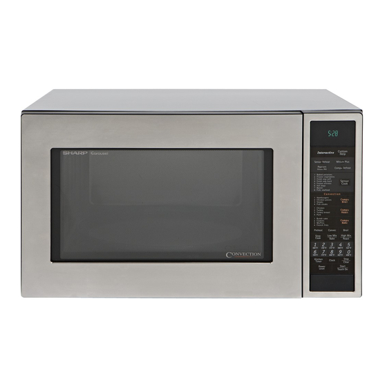
CONVECTION
MICROWAVE OVEN
R-930CS
MODEL
This document has been published to be used for after
sales service only.
The contents are subject to change without notice.
R-930CS
S9913R930CPST
Page
Advertisement
Table of Contents

Related Manuals for Sharp R-930CS


Summary of Contents for Sharp R-930CS
-
Page 1: Table Of Contents
R-930CS SERVICE MANUAL S9913R930CPST CONVECTION MICROWAVE OVEN Custom Interactive Help Sensor Reheat Minute Plus Popcorn Compu Defrost Elevate PKG 1 Baked potatoes 2 Frozen vegetables Sensor 3 Fresh veg-soft 4 Fresh veg-hard Cook 5 Frozen entrees 6 Hot dogs 7 Bacon... -
Page 2: Precautions To Be Observed Before And During Service To Avoid Possible Exposure To Excessive Microwave Energy
Before servicing an operative unit, perform a microwave emission check as per the Microwave Measurement Procedure outlined in this service manual. If microwave emissions level is in excess of the specified limit, contact SHARP ELECTRONICS CORPORATION immediately @1-800-237-4277. If the unit operates with the door open, service person should 1) tell the user not to operate the oven and 2) contact SHARP ELECTRONICS CORPORATION and Food and Drug Administration's Center for Devices and Radiological Health immediately. -
Page 3: Warning To Service Personnel
R-930CS WARNING TO SERVICE PERSONNEL Microwave ovens contain circuitry capable of pro- ducing very high voltage and current, contact with following parts may result in a severe, possibly fatal, electrical shock. (Example) High Voltage Capacitor, High Voltage Power Trans- former, Magnetron, High Voltage Rectifier Assem- bly, High Voltage Harness etc.. -
Page 4: Microwave Measurement Procedure
R-930CS MICROWAVE MEASUREMENT PROCEDURE A. Requirements: 1) Microwave leakage limit (Power density limit): The power density of microwave radiation emitted by a microwave oven should not exceed 1mW/cm at any point 5cm or more from the external surface of the oven, measured prior to acquisition... -
Page 5: Foreword And Warning
GENERAL INFORMATION R-930CS FOREWORD OPERATION This Manual has been prepared to provide Sharp Electronics Corp. Service Personnel with Operation and Service Information for the SHARP CONVECTION MICROWAVE OVEN, R-930CS. TROUBLESHOOTING GUIDE It is recommended that service personnel carefully study the entire... -
Page 6: Product Specifications
R-930CS SPECIFICATION ITEM DESCRIPTION Power Requirements 120 Volts 13.0 Amperes (Microwave) / 13.0 Amperes (Convection) 60 Hertz / Single phase, 3 wire grounded Power Output 900 watts (IEC 705 Test Procedure) Operating frequency of 2450MHz Convection Power Output 1450 Watts Case Dimensions Width 24-5/8"... - Page 7 R-930CS Electrical Requirements The electrical requirements are a 115 -120 volt 60 Hz, AC only, Grounded 3-Pronged Plug Receptacle Box 15 or 20 amp. fused electrical supply. It is recommended that a separate circuit serving only this appliance be provided. When installing this appliance, observe all applicable codes and ordinances.
-
Page 8: Operation
1. The display will show "SHARP SIMPLY THE BEST (1) When the door opens from a closed position, the primary PRESS CLEAR AND PRESS CLOCK". - Page 9 R-930CS motor and convection motor are turned on. to zero. 2. The coil of relay (RY4) is energized by the control unit. 2. The shut-off relays (RY1,RY2,RY3,RY5 and RY6) are The damper is moved to the closed position, opening the energized, turning on the oven lamp, turntable motor, damper switch contacts.
- Page 10 R-930CS An example of how sensor works: convection temperature, the oven goes into the programmed cooking mode. 1. Potatoes at room temperature. 6. At the end of the COMPU BROIL/ ROAST/ BAKE cycle, Vapor is emitted very slowly. the damper is returned to the open position and the oven will go to the off condition.
-
Page 11: Schematic Diagram
R-930CS IMPORTANT: detected vapors and initiated a sensor cooking cycle. During sensor cooking operation, the fire sensing op- This is because the operation of the convection fan eration sequence will not begin until the AH sensor has would interfere with the AH sensor's vapor detection. -
Page 12: Description And Function Of Components
R-930CS SCHEMATIC 1. DOOR CLOSED. 2. MIX COOKING PAD TOUCHED. 3. COOKING TIME PROGRAMMED. 4. “START” PAD TOUCHED. MAGNETRON CONV. 5. RY2 AND RY3 WILL ALTERNATELY CLOSE. TEMPERATURE THERMAL FUSE CUT-OUT DURING COOK CYCLE. FUSE COM. POWER (RY1) TRANSFORMER N.O. - Page 13 R-930CS is firmly closed thereby activating both interlock switches. The condition develops in the magnetron due to cooling fan primary interlock system consists of the door sensing switch failure, obstructed air guide, dirty or blocked air intake, etc. and primary interlock relay located on the control circuit board.
-
Page 14: Troubleshooting Guide
R-930CS air is channelled through the cavity to remove steam and switch is OFF), its signal is sensed by the control vapors given off from the heating foods. It is then exhausted unit, and shut-off relay (RY4) is de-energized. at the top of the oven cavity into a condensation compartment. - Page 15 R-930CS (SENSOR CONDITION OFF CONDITION COOKING CONDITION (MICROWAVE) (CONVECTION) COOKING) POSSIBLE CAUSE DEFECTIVE PARTS MAGNETRON POWER TRANSFORMER H.V. RECTIFIER ASSEMBLY HIGH VOLTAGE CAPACITOR SECONDARY INTERLOCK SWITCH PRIMARY INTERLOCK SYSTEM MONITOR SWITCH MONITOR FUSE MAGNETRON TEMPERATURE FUSE CONV. THERMAL CUT-OUT CONVECTION HEATER...
-
Page 16: Test Procedure
R-930CS TEST PROCEDURES PROCEDURE COMPONENT TEST LETTER MAGNETRON ASSEMBLY TEST 1. Disconnect the power supply cord, and then remove outer case. 2. Open the door and block it open. 3. Discharge high voltage capacitor. 4. To test for an open filament, isolate the magnetron from the high voltage circuit. A continuity check across the magnetron filament leads should indicate less than 1 ohm. - Page 17 R-930CS TEST PROCEDURES PROCEDURE COMPONENT TEST LETTER (HIGH VOLTAGES ARE PRESENT AT THE HIGH VOLTAGE TERMINAL, SO DO NOT ATTEMPT TO MEASURE THE FILAMENT AND HIGH VOLTAGE.) HIGH VOLTAGE RECTIFIER TEST 1. Disconnect the power supply cord, and then remove outer case.
- Page 18 R-930CS TEST PROCEDURES PROCEDURE COMPONENT TEST LETTER 5. Reconnect all leads removed from components during testing. 6. Reinstall the outer case (cabinet). 7. Reconnect the power supply cord after the outer case is installed. 8. Run the oven and check all functions.
- Page 19 R-930CS TEST PROCEDURES PROCEDURE COMPONENT TEST LETTER 5. Reconnect all leads removed from components during testing. 6. Reinstall the outer case (cabinet). 7. Reconnect the power supply cord after the outer case is installed. 8. Run the oven and check all functions.
- Page 20 R-930CS TEST PROCEDURES PROCEDURE COMPONENT TEST LETTER THERMISTOR TEST 1. Disconnect the power supply cord, and then remove outer case. 2. Open the door and block it open. 3. Discharge high voltage capacitor. 4. Disconnect connector-E from the control unit. Measure the resistance of the thermistor with an ohmmeter.
- Page 21 R-930CS TEST PROCEDURES PROCEDURE COMPONENT TEST LETTER 9. Open the door and block it open. 10.Discharge high voltage capacitor. 11.Reconnect all leads removed from components during testing. 12.Re-install the outer case (cabinet). 13.Reconnect the power supply cord after the outer case is installed.
- Page 22 R-930CS TEST PROCEDURES PROCEDURE COMPONENT TEST LETTER 2. Control Unit The following symptoms indicate a defective control unit. Before replacing the control unit, perform the Key unit test (Procedure Q) to determine if control unit is faulty. Reconnect the power supply cord.
- Page 23 R-930CS TEST PROCEDURES PROCEDURE COMPONENT TEST LETTER RELAY TEST 1. Disconnect the power supply cord, and then remove outer case. 2. Open the door and block it open. 3. Discharge high voltage capacitor. 4. Disconnect the leads to the primary of the power transformer.
- Page 24 R-930CS TEST PROCEDURES PROCEDURE COMPONENT TEST LETTER 3) Discharge high voltage capacitor. 4) Follow the troubleshooting guide given below for repair. STEPS OCCURRENCE CAUSE OR CORRECTION Only pattern at "a" is broken. *Insert jumper wire J1 and solder. Pattern at "a" and "b" are broken.
- Page 25 R-930CS TEST PROCEDURES PROCEDURE COMPONENT TEST LETTER permit adequate ventilation, be sure to install so as not to block these vents. There should be some space for air circulation. (5) Be sure the exterior of the cooking container and the interior of the oven are dry. Wipe off any moisture with a dry cloth or paper towel.
- Page 26 R-930CS TEST PROCEDURES PROCEDURE COMPONENT TEST LETTER (8) After that procedure, re-connect the power supply cord. (9) Check the sensor cook operation proceed as follows: 9-1. Touch SENSOR COOK pad and then touch the number pad 1. And touch Start pad.
-
Page 27: Touch Control Panel
R-930CS TOUCH CONTROL PANEL ASSEMBLY OUTLINE OF TOUCH CONTROL PANEL The touch control section consists of the following units 4) ACL Circuit as shown in the touch control panel circuit. A circuit to generate a signals which resetting the LSI to the initial state when power is applied. - Page 28 R-930CS Pin No. Signal Description Used for initial balancing of the bridge circuit (absolute humidity sensor). This input is an analog input terminal from the AH sensor circuit, and connected to the A/D converter built into the LSI. AH sensor input.
- Page 29 R-930CS Pin No. Signal Description Damper motor relay driving signal. H : GND To turn on and off shut-off relay(RY4). Heating element driving signal. To turn on and off shut-off relay(RY3). "L" level During during convection cooking; "H" level otherwise. Dur- cooking ing convection cooking, the signal becomes "H"...
- Page 30 R-930CS Pin No. Signal Description Segment data signals. The relation between signals and indicators are as follows: Signal Segment Signal Segment Signal Segment Signal Segment P23 ..... P1 P17 ..... P5 P13 ..... P9 P07 ... P13 P22 ..... P2 P16 .....
- Page 31 R-930CS ABSOLUTE HUMIDITY SENSOR CIRCUIT With this voltage given, the switches SW1 to SW5 in the (1) Structure of Absolute Humidity Sensor LSI are turned on in such a way as to change the The absolute humidity sensor includes two thermistors resistance values in parallel with R50-1.
- Page 32 R-930CS TOUCH CONTROL PANEL SERVICING 1. Precautions for Handling Electronic Components 5) Re-connect the power supply cord after the outer case is This unit uses CMOS LSI in the integral part of the circuits. installed. When handling these parts, the following precautions should 6) Run the oven and check all functions.
-
Page 33: Component Replacement And Adjustment Procedure
4. If the outer case (cabinet) is not fitted. WARNING FOR WIRING To prevent an electric shock, take the following pre- 3) Sharp edge: cautions. Bottom plate, Oven cavity, Waveguide flange, 1. Before wiring, Chassis support and other metallic plate. - Page 34 R-930CS CAUTION: 1. DISCONNECT OVEN FROM POWER SUP PLY BEFORE REMOVING OUTER CASE. 2. DISCHARGE THE HIGH VOLTAGE CA- PACITOR BEFORE TOUCHING ANY OVEN COMPONENTS OR WIRING. NOTE: When replacing the outer case, the 2 special Torx screws must be reinstalled in the same Special screw locations.
- Page 35 R-930CS 7. Remove one (1) screw and washer holding the rectifier the rear cabinet. from the capacitor holder. 9. Remove the capacitor from the holder. 8. Remove one (1) screw holding the capacitor holder to ® POSITIVE LOCK CONNECTOR (NO-CASE TYPE) REMOVAL Terminal 1.
- Page 36 R-930CS HEATER UNIT ASSEMBLY REMOVAL (HEATING ELEMENT/CONVECTION FAN/CONVECTION MOTOR/THERMISTOR) THERMISTOR REMOVAL HEATING ELEMENT REMOVAL 1. Disconnect the power supply cord and then remove 10.Remove two (2) screws holding heating element to outer case. heater duct. 2. Open the oven door and block it open.
- Page 37 R-930CS 16.Remove the fan blade from the fan motor shaft according 3. Hold the center of the bracket which supports the shaft the following procedure. of the fan motor on the flat table. 17.Hold the edge of the rotor of the fan motor by using a pair 4.
- Page 38 R-930CS misadjustment, the following adjustment should be made. 4. Loosen the two (2) screws holding latch hook to the oven cavity front flange. 5. With door closed, adjust latch hook by moving it back and DOOR SENSING forth, and up and down. In and out play of the door SWITCH allowed by the latch hook should be less than 0.5mm.
-
Page 39: Door Disassembly
R-930CS DOOR DISASSEMBLY DOOR PANEL Remove door assembly, refer to "Door Replacement". 5. Remove the twelve (12) screws holding the door panel Replacement of door components are as follows: to the door frame. CHOKE COVER NOTE: The one (1) screw of the twelve (12) screws also 1. -
Page 40: Pictorial Diagram
R-930CS... -
Page 41: Control Panel Circuit
R-930CS 3.3k 3.3k 3.3k 3.3k 3.3k 3.3k 3.3k 100k 100k 3.3k 100k R100 3.3k 3.3k 3.3k 3.3k IZA797DR 4.7k 3.3kF (J7) 4.7k (J5) HZ4A2 220F (J3) /35v (J6) /50v 6.8k (J4) /50v 0.01 HZ5C2 (J2) /25v /35v 3.3k /50v /50v... -
Page 42: Printed Wiring Board
R-930CS (C81) R86(J8) (C80) (R45) (C45) (CN - D) (R47) (R48) (R49) (C46) (C47) (J7) (J5) (J3) (J2) (J4) (J6) CONV HEATER COM Figure S-3. Printed Wiring Board... -
Page 43: Parts List
R-930CS PARTS LIST Note: The parts marked " " may cause undue microwave exposure. The parts marked "*" are used in voltage more than 250V. REF. NO. PART NO. DESCRIPTION Q'TY CODE ELECTRICAL PARTS 1- 1 FACCDA075WRE0 Power supply cord... - Page 44 R-930CS REF. NO. PART NO. DESCRIPTION Q'TY CODE D20-26 VHD1SS270A/-1 Diode (1SS270ATA) D30-31 VHD1SS270A/-1 Diode (1SS270ATA) D70-77 VHD1SS270A/-1 Diode (1SS270ATA) RH-IZA797DRE0 RH-IZA495DRE0 VS2SB910MR/-4 Transistor (2SB910M) VSKRA101M//-3 Transistor (KRA101M) VSDTA123ES/-3 Transistor (DTA123E) Q20-23 VSKRA101M//-3 Transistor (KRA101M) Q24-25 VSKRA223M//-3 Transistor (KRA223M) VSKRC243M//-3...
- Page 45 R-930CS REF. NO. PART NO. DESCRIPTION Q'TY CODE 4-22 NCPL-A021WRF0 Turntable coupling 4-23 PCOVPA301WRE0 Waveguide cover 4-24 PCUSUA197WRP0 Cushion 4-25 PGLSPA455WRE0 Light glass 4-26 PFPF-A139WRE0 Thermal protection sheet (Right) 4-27 PREFHA053WRW0 Thermal protection plate (Right) 4-28 PSKR-A153WRW0 Air guide (Bottom)
-
Page 46: Packing And Accessories
1. MODEL NUMBER 3. PART NO. 2. REF. NO. 4. DESCRIPTION Order Parts from the authrized SHARP parts Distributor for your area. Defective parts required return should be returned as indicated in the Service Policy. PACKING AND ACCESSORIES TRAY HOLDER... - Page 47 R-930CS OVEN AND CABINET PARTS...
- Page 48 R-930CS CONTROL PANEL PARTS 7-24 3-2-5 3-2-4 3-2-1 7-24 DOOR PARTS 3-2-3 3-2-2 5-12 5-13 5-11 5-11 5-11 5-10 5-11 MISCELLANEOUS Actual wire harness may be different than illustration. '99 SHARP CORP. (9S2.530E) Printed in U.S.A...
- Page 49 No part of this publication may be repro- duced, stored in retrieval systems, or trans- mitted in any form or by any means, elec- tronic, mechanical, photocopying, record- ing, or otherwise, without prior written per- mission of the publisher. '99 SHARP CORP. (5S2.530E) Printed in U.S.A...
Need help?
Do you have a question about the R-930CS and is the answer not in the manual?
Questions and answers
Our Sharp Carousel Convection Microwave (R-930CS) occasionally makes a low rattling noise while operating in the convection mode. At first I thought it might have been the glass carousel not seated correctly on its rail. But my wife believes the noise is coming from behind the "convection air opening" on the left side of unit's interior. If so, do you any suggestions of what might be making the sound and how to correct the problem? Thanks, Joe Loupe