Table of Contents
Advertisement
Quick Links
Advertisement
Table of Contents

Subscribe to Our Youtube Channel
Related Manuals for Bartec PSB


Summary of Contents for Bartec PSB
- Page 1 Design Guide Self-regulating trace heating systems for hazardous / industrial applications Design guide BARTEC Self-regulating trace heating systems for pipes and tanks in hazardous locations with BARTEC self-regulating trace heating cables PSB and MSB Origin Design Guide...
-
Page 3: Table Of Contents
Table of content Installation self-regulating trace heaters on pipes and vessels 30 Design Guide Preparation Self-regulating trace heating systems for hazardous / industrial applications Required tools / equipment Overview Unrolling the trace heater Applications Installation on pipes Certifications / Approvals / Marking Fastening Safety Trace heater routing... -
Page 4: Overview
Self-regulating trace heating systems Design Guide for Hazardous / Industrial Overview This manual covers the design and general installation of BARTEC Self-regulating trace heating systems for use in hazardous locations using the following self-regulating heating cables, hereinafter called trace heaters: BARTEC PSB (07-5853-*) ... -
Page 5: Applications
BARTEC Self-regulating trace heating systems Danger of burning due to electric heating system types PSB or MSB in combination with BARTEC splice kits and junc- Danger of burning from hot surface tion boxes as follows:... -
Page 6: Specific Conditions Of Use
Connections and terminations for installation with the Self-Regulating port”). Heating Cable Series PSB and MSB shall be certified according to the When used in TT and TN systems a residual current device according requirements of the applicable standards for the types of protection for to IEC/IEEE 60079 30-1, clause 4.4 point c) 1) shall be installed. -
Page 7: Applicability
Applicability This document covers the design of BARTEC PSB and MSB trace heating systems. It includes mainly engineering procedures for certified com- ponents as set out in section System design. The manuals shipped together with the individual components will contain additional relevant content to this document. -
Page 8: Technical Data
Self-regulating trace heating systems Design Guide for Hazardous / Industrial Technical data Self-regulating trace heating system II 2G Ex db eb mb [ib] 60079-30-1 IIC T6…T3 Gb Protection classification II 2D Ex tb [ib] 60079-30-1 IIIC T 80 °C… T 170 °C Db Trace heater Max. -
Page 9: Trace Heater Installation Enclosure As Power Box Kit
-55 °C to +55 °C -40 °C Min. installation temperature -55 °C -40 °C MSB: PSB: Power supply cable 70 °C @ Ta max 40 °C 70 °C @ Ta max 40 °C Service temperature at con- 80 °C @ Ta max 55 °C 85 °C @ Ta max 55 °C... -
Page 10: Trace Heater Installation Enclosure As End Of Line Light Kit And End Of Line Seal Kit
Power supply Ambient temperature range -55 °C to +55 °C Min. installation temperature -55 °C -55 °C PSB: MSB: Minimum Temperatur re- +80 °C for system in T5 +125 °C for system in T3 sistance of supply cable +75 °C for system in T6 +95 °C for system in T4... -
Page 11: System Design
Step 1: Familiarize yourself with the trace heater types and their properties BARTEC self-regulating trace heaters are available in various types to suit different applications. Each trace heater is marked with a product code that contains relevant information as shown in the following example:... - Page 12 Ambient temperature: -20 °C Outdoor installation, wind speed: 20 m/s Application of a safety factor of +10 % For other values contact your local BARTEC distributor. 21-1S00-7D0001/- Notice Technical data subject to change without notice. Page 10 / 42 05/2023-EHT-466853 No claims for damage arising from alternations, errors or misprints shall be allowed.
- Page 13 Finally, you must apply the following correction factors depending on your insulation material: Table B: Insulation Correction Factors thermal conductivity at 20 °C Correction Factor* in W/m × Rockwool / Mineral Fibre (ASTM C547-15 Type II) 1.00 0.0370 Calcium Silicate (ASTM C533 Type I) 1.47 0.0567 Cellular glass (ASTM C552-15 Type II)
- Page 14 NOTICE If you want to use plastic piping within your installation, contact your local BARTEC distributor for verification that the design does not exceed the maximum withstand temperature of the pipe material. Also, adjustments in heat loss calculations may be required.
- Page 15 Use a thicker insulation or insulation material with a lower thermal conductivity. Contact your local BARTEC distributor for further assistance. → Example Trace heater family as determined in Step 3: PSB Power supply voltage: 230 V Maintain temperature: 25 °C ...
- Page 16 Self-regulating trace heating systems Design Guide for Hazardous / Industrial Table D: PSB 230V For MSB trace heaters see next page. 21-1S00-7D0001/- Notice Technical data subject to change without notice. Page 14 / 42 05/2023-EHT-466853 No claims for damage arising from alternations, errors or misprints shall be allowed.
- Page 17 Table E: MSB 230V For PSB trace heaters see previous page. 21-1S00-7D0001/- Notice Technical data subject to change without notice. Page 15 / 42 05/2023-EHT-466853 No claims for damage arising from alternations, errors or misprints shall be allowed.
-
Page 18: Determination Of The Required Trace Heater Length
Step 5: Select the appropriate outer jacket material BARTEC self-regulating trace heaters are available with 2 different types of outer jackets. Choose the outer jacket that suits the chemical envi- ronment it will be exposed to. For questions regarding the chemical resistance please contact your local BARTEC distributor. -
Page 19: Determination Of The Required Number Of Heating Circuits
→ Example total required trace heater length: 63.3 m circuit breaker voltage: 230 Vac selected trace heater: 10 PSB circuit breaker amperage: 25 A required start-up temperature: -20 °C allowable trace heater length from table below = maximum of 69 m at -20 °C on 25 A circuit breaker at 230 Vac = 63.3 m calculated <... - Page 20 If feeding multiple trace heating system circuits from the single circuit breaker, the maximum sum of trace heater lengths can then be extended. Please refer to BARTEC Heloc Pro design software or contact BARTEC technical support. Breaker sizing should be based on international electric codes or any other local or applicable code. Use only circuit breakers with type C tripping characteristics.
-
Page 21: Selection Of The Required Components For Power Connection, Control And Monitoring, End Termination Etc
Step 12: Determine if control equipment is required: BARTEC provides a variety of control products, from simple mechanical thermostats to sophisticated digital controllers and control and monitor- ing systems designed specifically for use with our trace heating products. This section will help you select and specify the right control products for your application. - Page 22 Self-regulating trace heating systems Design Guide for Hazardous / Industrial Ambient sensing control: uses an on-off thermostat that senses ambient temperature Ambient temperature sensor is more energy efficient than self-regulating control because the heating circuit is energized only when the temperature Ambient sensing control drops below the set-point is most suitable for freeze-protection applications where...
- Page 23 Base your selection on the number and type of trace heating circuits to be installed, the type of control you need, and the area classification. TABLE K: Control Equipment Selection Recommendations Heating circuit type Application Control options Suitable BARTEC control product Quantity required Self-regulating heating circuits on pipes Freeze protection Ambient-sensing...
- Page 24 BARTEC recommends to always use, at a minimum, ground-fault monitoring. For the small additional cost, you get a monitoring system that ...
- Page 25 Base your selection on the number and type of trace heating circuits to be installed, the type of continuity monitoring you need, and the area classification: TABLE L: Monitoring Equipment Selection Recommendations Heating circuit type Application Monitoring options Suitable BARTEC monitoring product Quantity required ELS-200 High profile end seal or Freeze protection 1 per circuit...
- Page 26 PLEXO Plug-in splice kit Adhesive tape The following pages list compatible components for BARTEC Self-regulating trace heating systems in hazardous / industrial locations. The re- spective installation instructions are included in the scope of delivery. 21-1S00-7D0001/- Notice Technical data subject to change without notice.
-
Page 27: Trace Heaters
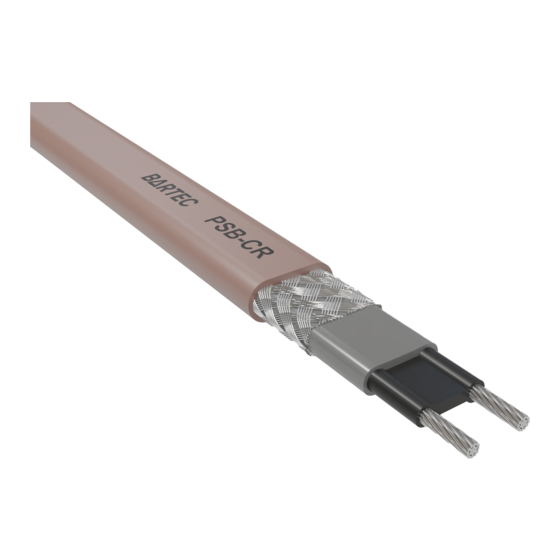
Trace heaters PSB trace heater with polyolefin outer jacket 120 Vac Catalog No.: Order No.: Part No.: Self-regulating trace heater for installation on 10 W/m 3PSB1-CR 439493 07-5853-110P pipes, tanks etc. 15 W/m 5PSB1-CR 439494 07-5853-115P 25 W/m 8PSB1-CR 439495... -
Page 28: Power Connection, Splice And Junction Components
Self-regulating trace heating systems Design Guide for Hazardous / Industrial Power connection, splice and junction components PBS-200-E/E10 Single power entry con- PBS-200-E: nection kit "on pipe" Catalog No.: PBS-200-E Part No.: 27-54P2-42221B10 For connection of a trace heater inside a junction PBS-200-E10: box. -
Page 29: Control And Monitoring Units
for ease of maintenance at pumps and ves- sels.. The kit is approved for Zone 1 and Zone 2 areas. For a complete list of kit contents, approvals and additional configurations see data sheet. Control and monitoring units PBTW Mechanical thermostat for hazard- Sensor temperature range -20 °C to 50 °C: Catalog No.: PBTW-200-E050 ous locations (on-pipe installation) -
Page 30: End Termination
CAK-E5: Catalog No.: CAK-E5 Silicone end seal for insulation of the end of Part No.: 27-59CZ-90000005 the trace heater. Suitable to all Bartec paral- lel trace heating cable. Approved accordingly CAK-E10: IECEx, ATEX, CSA (ordinary and hazardous Catalog No.: CAK-E10 Part No.: 27-59CZ-90000010... -
Page 31: Spare Parts
Off pipe cable gland kit and end seal CAK-SRG-B with cable gland FG-S-1 Catalog No.: CAK-SRG-B with FG-S-1 for use with heating cable PSB, MSB, HSB+, HTSB Part No.: 27-59CX-97010001 CAK-SRG-C with cable gland FG-S-C Catalog No.: CAK-SRG-C with FG-S-C for use with heating cable PSB, MSB, HSB+, HTSB;... -
Page 32: Installation Self-Regulating Trace Heaters On Pipes And Vessels
This step is necessary for plastic pipes only since plastic pipes conduct heat loss efficiently than metal pipes do. For metal pipes The following tools are required for installation of the BARTEC Self- refer to step 4. regulating trace heating systems: Place aluminium tape where the trace heater will be attached for ... -
Page 33: Fastening
Avoid water accumulation in the mounting stand! BARTEC recommends applying the pipe insulation immediately after installing the junction box and the mounting stand. Fastening... - Page 34 Self-regulating trace heating systems Design Guide for Hazardous / Industrial Installation of service loops on components: Installation on flanges: Installation on valves: Installation on pipe supports: Installation on pressure gauges: 21-1S00-7D0001/- Notice Technical data subject to change without notice. Page 32 / 42 05/2023-EHT-466853 No claims for damage arising from alternations, errors or misprints shall be allowed.
-
Page 35: Installation On Tanks And Vessels
Installation on pumps: Installation on tanks and vessels For tank diameters of up to 2 m the trace heater is attached using polyester fixing straps and tensioning buckles. To fasten the fixing straps thread the polyester straps through the tensioning buckle as shown and pull the ends of the straps. ... - Page 36 Self-regulating trace heating systems Design Guide for Hazardous / Industrial At first, install fixing straps around the beginning and end of the tank and fasten them with slight tension. Upright tank Horizontal tank Install the trace heater beginning at the supply point. ...
- Page 37 Align the trace heater exactly and fix it firmly to the bases and the cylinder using additional fixing straps. To avoid damage to the trace heater, make sure that the fixing straps are not tightened too firmly. It should be possible to move the trace ...
-
Page 38: Tests And Commissioning
Insulation resistance values for Test 1 and 2; for any particular circuit, should not vary more than 25 percent as a function of measuring volt- age. Greater variances may indicate a problem with your trace heating system; confirm proper installation and/or contact your local BARTEC representative for assistance. -
Page 39: Acceptance Test And Acceptance Test Report
This documentation should include the following: Project planning documents Results of design calculation e.g. summarized in Print out of Heloc Pro calculation or Manual calculation documented e.g. in BARTEC template 21-1000-7E0001 (www.bartec.com) In detail: Trace heating circuit identification... -
Page 40: Maintenance
Self-regulating trace heating systems Design Guide for Hazardous / Industrial Maintenance Visual and functional inspection Regularly check the thermal insulation for possible damage, missing seals, cracks, damage to the outer jacket, missing thermal insulation bushings for trace heaters and cables, penetrated water or chemicals. If the thermal insulation is damaged the trace heater should be checked for possible damage. -
Page 41: Checklist Customized Entry Port
For installation of selected components, the manufacturer’s installation manual must be observed. Thus above mentioned advices may differ. It must be added to the junction box documentation. It is not allowed to add or manipulate drillings and threads at the BARTEC junction box. For selecting type of Power supply cable, see chapter Technical Data. -
Page 42: Acceptance Report / Record Of Inspection
Inspection after modification Periodic inspection Visual inspection Close inspection Detailed inspection Project information Project / Customer Order Comm. No. / BARTEC Order No. Date Installation details Electric Trace Heating of Pipes Electric Trace Heating of Tanks/Vessels Heating circuit type Zone... -
Page 43: Troubleshooting
Troubleshooting Problem Possible cause Remedy Trace heater remains No power supply Check the power wiring for continuity to circuit breaker. cold Trace heater bus wires or power wiring Connect the trace heater and power wiring according to the installa- not properly connected tion instructions. -
Page 44: Limited Product Warranty (Worldwide, Excepting North America)
Scope BARTEC warrants that all BARTEC products and accessories that are the subject of this manual will be free from defects in materials and work- manship from and after its date of purchase for a period of 12 (twelve) months. - Page 46 BARTEC GmbH Phone: +49 7931 597-0 GLOBAL HEADQUARTERS Max-Eyth-Straße 16 Fax: +49 7931 597-499 97980 Bad Mergentheim info@bartec.com Germany www.bartec.com...
Need help?
Do you have a question about the PSB and is the answer not in the manual?
Questions and answers