Advertisement
Quick Links
Advertisement

Related Manuals for KAYO MOTO S200


Summary of Contents for KAYO MOTO S200
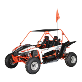
- Page 1 KAYO MOTO S200 Assembly Manual...
- Page 2 WWW.KAYOMOTO.COM...
- Page 3 ① 8 #wrench ② 10 # wrench ③13 # wrench ④ 14 # wrench ⑤ 12 # T sleeve ⑥ 19 # wrench ⑦ 21 # wrench ⑧Cross screwdriver ⑨ 12mm socket ⑩ 13mm socket ⑪ 14mm socket ⑫ 17mm socket ⑬...
- Page 4 3. Use ⑰ (Needle nose pliers or side cutters) to cut the wire ties and metal wires ,take out the parts fixed on the vehicle and metal crate, use ⑪ (14mm socket) to remove the metal crate bolts, Waiting for subsequent installation. Name Quantity A F/R wheel essy.
- Page 5 5.The picture shows the parts and standard parts of 4.4 accessory box. Please read the instructions before install and follow the steps above to install the vehicle Name Quantity Fixing screws and nuts of M10 * 30 * 1.5 bolts and 2 upper suction pipe and M10 * 1.5 self-locking nuts upper cross bar of backrest...
- Page 6 S Ceiling cloth and flag T Seat fixing nuts U Flag pole fixed base Upper suction pipe lower Φ51-70 fixing clamp Front protective fixing M8 * 12 bolts screws X Tire dust cover Backrest cross bar fixing M8 * 16 bolts screws Φ10.1*20*H9 Fixing bushing for upper...
- Page 7 8. Raise the rear body, install the upper end of L (rear shock assembly) on the rear shock mounting base of the frame, and use ⑭ (torque wrench) ⑩(13mm socket) ④(14 # wrench) to tighten N ( M10 * 1.25 bolts*2 and M10 * 1.25 nuts*2) fixing screws (the bolts are front, the nuts are back, and the torque requirement is 49-59 N·m).
- Page 8 11.The rear wheel is wider than the front wheel as shown above. Install all the four wheels to the appropriate hub, use tool ⑫ (No. 17# socket) ⑭ (torque wrench) ⑬(Extension rod of socket)to tighten k ( nut M10*1.25 60°16pcs) and fix screw,bolt taper toward the hub (torque requirement 55-66 N m)
- Page 9 12.As shown in the picture, install the front guard at the front of the frame, and use tool ⑨ (12mm socket) ⑭ (torque wrench) to tighten W (M8 * 12 bolts*4) and J (Φ 8 * 13 * 2 spring washer*4) fixing screws (torque requirements 25-30 N·m).
- Page 10 15. As shown in the picture, align the mounting screw of C (seat) with the mounting hole of the frame, and screw it with tool ⑨(12mm socket), ⑬(extension rod of socket), ⑭ (torque wrench) and T (self-locking nuts M8*8) (torque requirement is 25-30 N·m).
- Page 11 18. As shown in the picture, align the fixing end of F (ceiling beam) inside and the beam outside, and use tool ⑮ (6 # hexagonal socket wrench) and screw O (M8 * 16 hexagonal socket bolts*8) to tighten. 19. As shown in the picture, align G (backrest beam) with ceiling frame mounting base, and use tool ⑨(12mm socket) ⑭...
- Page 12 22. As shown in the picture, use tool ⑤(12 # T- shaped sleeve) to unscrew the angle adjusting screw of the steering wheel, adjust the steering wheel to a proper position, and re-tighten it. 23. As shown in the picture, install U (flag pole fixing base) to the mounting hole at the end of the frame, insert H (flag pole) into the flag pole fixing base, tighten it with tool ⑥(19 # wrench), and...
- Page 13 25. As shown in the picture, install X (tire dust cover) on the front and rear wheels without gaps. 26. Unscrew the fuel tank cap, add gasoline, and tighten the fuel tank cap clockwise. 27.Use tool ⑧(Cross screwdriver) to loosen the two bolts on the upper end of the instrument panel, gently remove the cover of the cover fix bolt cart head, unscrew the battery wiring bolt, insert it...
Need help?
Do you have a question about the S200 and is the answer not in the manual?
Questions and answers