Table of Contents
Advertisement
Quick Links
Advertisement
Table of Contents

Subscribe to Our Youtube Channel
Related Manuals for Abus TVHS30000


Summary of Contents for Abus TVHS30000
- Page 1 TVHS30000 Operating instructions Software Version 06/2023...
- Page 2 These operating instructions contain important information on commissioning and handling. Pay attention to this, even if you pass this product on to third parties. Therefore, keep these operating instructions for future reference! A list of the contents can be found in the table of contents with the corresponding page numbers on page 8.
- Page 3 TVHS30000 Operating instructions Version 06/2023 Original operating instructions in German. Keep for future use!
- Page 4 ABUS Security-Center GmbH & Co KG accepts no liability for technical and typographical errors and reserves the right to make changes to the product and operating instructions at any time without prior notice.
- Page 5 Explanation of symbols The symbol with the lightning bolt in the triangle is used when there is danger to the health exists, e.g. due to electric shock. An exclamation mark within the triangle is intended to alert the user to the presence of important instructions in this manual that should be followed.
- Page 6 Power supply: Pay attention to the information on the type plate for the supply voltage and power consumption. Overload Avoid overloading mains sockets, extension cords and adapters as this may cause a fire or electric shock. Cleaning Clean the unit only with a damp cloth without harsh detergents. The unit must be disconnected from the mains.
-
Page 7: Table Of Contents
Initial commissioning ......................11 6.1 Activating the unit via the local touch monitor................11 6.2 Activating the device via the ABUS IP Installer ................ 11 6.3 Activating the unit via the web browser ..................12 6.4 Install Video Plugin ........................13 Configuration and operation via the touch monitor ............ - Page 8 8.1.3.5 HTTP Socket ........................41 8.1.4 Video ............................. 42 8.1.4.1 Video ..........................42 8.1.4.2 Audio ..........................43 8.1.4.3 Audio output ........................43 8.1.5 Image ............................. 44 8.1.6 General ..........................46 8.1.6.1 Authentication settings......................46 8.1.6.2 Data protection ........................48 8.1.6.3 Face recognition parameters ....................49 8.1.6.4 Card security ........................
-
Page 9: Intended Use
1. Intended use The FaceXess device is used indoors or outdoors as an access control system with facial recognition combined with a video door communication system. Any use other than that described above may result in damage to the product, and there are also other dangers. -
Page 10: Features And Functions
Unknown persons are not recorded. See, Speak, Open ABUS FaceXess is easy to operate intuitively. The 7-inch touch display with virtual bell button is the user interface of the door station. On the smartphone (ABUS Link Station app) or the optional indoor monitor, you can see who is at the door, talk to the person and switch the electric strike. -
Page 11: Device Description
For this method of activation, the unit must first be integrated into the IP network. This is done via the wired network connection (LAN connection). The IP address is assigned automatically via the DHCP protocol. Install and start the ABUS IP Installer. This is available via the ABUS website www.abus.com for the respective product. -
Page 12: Activating The Unit Via The Web Browser
For this method of activation, the unit must first be integrated into the IP network. This is done via the wired network connection (LAN connection). The IP address is assigned automatically via the DHCP protocol. The IP address that the device has been assigned by the DHCP server can be viewed via the ABUS IP Installer. -
Page 13: Install Video Plugin
6.4 Install video plugin To install the video plug-ins, you need the appropriate rights on the PC. Edge (Internet Explorer Mode) / Internet Explorer A so-called ActiveX plugin is used for the video display in Internet Explorer. This plug-in must be installed in the browser. -
Page 14: Configuration And Operation Via The Touch Monitor
7. Configuration and operation via the touch monitor The operation and configuration of the facial recognition terminal can be done directly via the display device by touch control (hereinafter referred to as "touch display"). 7.1 Setup Wizard The setup wizard guides you step by step through the most important menu items to get the unit ready for basic operation. -
Page 15: Main Operating Page
7.2 Main operating page 7.2.1 View options (themes) Standard: Only call button(s), pin code and QR code button are displayed during configuration, as well as the preview video of the person if desired. Simple: Only the call button(s), pin code and QR code button are displayed during configuration. -
Page 16: Symbols And Information Displays
In the upper right corner of the main view in the display there are four icons with the following information. Symbol Function Display of the active connection to the ABUS Link Station Cloud or active connection to an ABUS Link Station account. Icon:... -
Page 17: Administrator Menu
7.3 Administrator menu 7.3.1 User All configured users are displayed in the User Administration settings page. Each line provides information about the user name, ID, user type and which media are set up for the respective user. User administration If this character appears before the user name, this user has administrator rights. - Page 18 Super card: A super card always has access, even if special time periods are √ Normal map programmed for access via card (programming possible via ABUS Compulsory card CMS). Super map Patrol map: This map type is used for patrols...
- Page 19 (e.g. add more users or add opening media). Method > √ Normal user Administrator Access via the web interface or ABUS CMS software is only possible via the device password that was assigned during initial commissioning.
-
Page 20: Access Options
7.3.2 Access options Terminal Authorisation Mode: Specify the permitted authentication methods that are built directly into the device and can be used. A change in the terminalauthentication mode is Access options not applied to users who have already been taught in. It is therefore necessary to re-enrol users who have Terminal Auth. -
Page 21: Communication
Function not used Opening time (s): Setting the switching time for the relay (e.g. for electric door opener, wiring harness designation "LOCK") Authentication interval (s): Set the length of time before a new recognition of faces or cards takes place. After the 1st detection, this time voltage is first waited for. - Page 22 RS-485 Activation and configuration of the RS-485 interface. This interface can be used, for example, to enable an ABUS security module (TVAC20340) for the secure connection of an electric door opener. Door opener can be enabled. As soon as the RS-485 option "control unit" has been selected, the terminal must be restarted after exiting the menu.
-
Page 23: Basic Settings
The following setting is necessary for the call function from terminal to app: Local Display Menu: Admin Menu / Display / Quick Key / Call App Web interface: Admin login / Configuration / Intercom / Call button / 7.3.4 Basic settings Voice settings / sound settings General settings ... -
Page 24: Biometric
7.3.5 Biometric Application mode Biometrics Select in which area the terminal was installed Application mode Interior > (inside, outside). Depending on the selection, certain presettings are made for the unit and in particular for Face Authenticity Level Normal > the camera module. - Page 25 ECO Threshold:The higher the value, the faster the ECO mode is used by the terminal. ECO mode (1:1): Analogue normal 1:1 security level. ECO mode (1:N): Analogue normal 1:N security level. Face with mask recognition After activating this function, the terminal checks whether a detected person is wearing a mouth-nose protection (colloquially "mask").
-
Page 26: Database
7.3.6 Database Delete data Delete user data: Delete all taught-in users. Data management The user administration is then empty. Access to the Delete data > administrator menu is then only possible with the Import data > admin password of the unit. Export data >... -
Page 27: System Maintenance
7.3.7 System maintenance System information This page displays various information of the unit (unit model, serial number, firmware version, MAC address, production date, unit QR code, open source information). The unit QR code is used for integration into the Link Station app. Capacity Display of the taught-in number of users, faces, cards and event entries (logbook) with the remaining amount available. -
Page 28: Representation
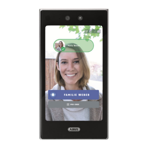
7.3.8 Representation Quick key Call: When activated, the display of Representation the unit shows at least one call button Quick key > Call Type: Central Call: Topic Normal > Call Specific Room Call Show video with unknown people Room no. Button name: FAMILY ONE ... -
Page 29: Configuration And Operation Via Web Browser
If the terminal is already successfully connected to a network via a network cable or the WiFi settings have been successfully programmed via the display, the web page of the terminal can be called up via a browser (preferably Chome, Edge). The IP address of the device can be found via the ABUS IP Installer described above. - Page 30 Live view parameters Stream type: Specify which video quality is to be displayed as the default in the "Live View" page. Main stream (1st video stream), high quality. Substream (2nd video stream), low quality Playback performance: This setting influences the buffering of the video stream. With "Lowest delay" there is hardly any buffering, with "Smooth"...
-
Page 31: System
Display of the serial number Device QR code: When this button is pressed, the serial number is displayed as a QR code. This makes it easier to add the terminal to the ABUS Link Station app. Firmware version: Display of the firmware version Cod. -
Page 32: Time Settings
8.1.2.1.2 Time settings Time zone Selecting the time zone (GMT) Time setting method NTP: Using the Network Time Protocol (NTP), it is possible to synchronise the camera's time with a time server.Activate NTP to use the function. Server address: IP server address of the NTP server. NTP Port : Network port number of the NTP service (default: port 123) NTP update interval:... -
Page 33: Dst / Summer Time
8.1.2.1.3 DST / Summer Time Summertime Activate daylight saving time: Select "Daylight Saving Time" to automatically adjust the system time to daylight saving time. Start time: Set the time for the changeover to daylight saving time. End time: Set the time for the changeover to winter time. Accept the settings you have made by clicking on "Save". -
Page 34: Maintenance
8.1.2.2 Maintenance 8.1.2.2.1 Updating and maintenance Restart: Click "Restart" to restart the unit. Restore parameters Default: Reset values except for IP parameters and user data. Restore All:Reset all values. Unlink App Account:This button unlinks the current terminal and Link Station Account. Export the unit parameters / the log file: Assign a password for the export file. -
Page 35: Protocol Query / Log Book
8.1.2.2 Protocol query / log book In this item, log information of the camera can be displayed. An SD card must be installed in the camera for log information to be saved. 8.1.2.3 Safety 8.1.2.3.1 Security service Activate SSH: This function activates the Telnet port and the Telnet protocol. Enable HTTP: Deactivation of the http interface for displaying the web page is possible. -
Page 36: User Administration
8.1.2.4 User administration Under this menu item you can change the password of the administrator user. To do this, click on the edit symbol at the back of line 1. To do this, you must enter the old password and enter and confirm the new password. Accept the settings you have made with "OK". -
Page 37: Network
8.1.3 Network 8.1.3.1 TCP/IP DHCP: If a DHCP server is available, click DHCP to automatically apply an IP address and other network settings. The data is automatically taken from the server and cannot be changed manually. If no DHCP server is available, please fill in the following data manually. IPv4 address: Setting the IP address for the network interface IPv4 Subnet Mask:... -
Page 38: Port
IPv6 Subnet Mask: Displays the IPv6 subnet mask. IPv6 Standard Gateway: Display of the IPv6 standard gateway (standard router) MAC address: The IPv4 hardware address of the terminal is displayed here; you cannot change this. MTU: Setting of the transmission unit, select a value 500 - 9676. 1500 is preset by default. -
Page 39: Wifi
Accept the settings you have made by clicking on "Save". 8.1.3.3 WiFi If the WiFi function was not activated during the local setup on the display, this can also be done here in the web interface. After activation, the system automatically searches for available WiFi access points (2.4 GHz only!). Select an access point, you will then be asked to enter the password of the access point (e.g. -
Page 40: Cloud Access / Abus Link Station
8.1.3.4 Cloud access / ABUS Link Station The ABUS Link Station function is used for easy remote access to the ABUS device via Link Station APP (iOS / Android). Products can be easily set up and released via QR code - without complicated configurations in the router (no port forwarding necessary). -
Page 41: Http Socket
8.1.3.5 HTTP Socket Event information can be sent to an alarm host via JSON Telegram. In this way, events can be transmitted to a third-party software for further processing. For easy testing of this function, the TCP server function of the software "Hercules Setup Utility"... -
Page 42: Video
8.1.4 Video 8.1.4.1 Video Video channel: Only the 1st camera can be changed in certain parameters. Camera name: By default, the serial number is assigned as the name. This name can be changed. Stream type: Select the stream type for the camera. Select "Main Stream (Normal)" for recording and live view with good bandwidth. -
Page 43: Audio
Accept the settings you have made by clicking on "Save". 8.1.4.2 Audio Audio channel: Only the audio part of camera 1 can be edited Steamtyp: The settings determine the audio settings for the main or sub-stream respectively. Audio coding: This is the audio codec used. Volume input: Volume of the audio input (Mic) Output volume:... -
Page 44: Image
8.1.5 Image Video standard: Set the video standard or the network frequency for the terminal's region of use here (PAL, 50 Hz, 25 frames/s or NTSC, 60 Hz, 30 frames/s). WDR: If the contrast between the background and the foreground (face) is too great, then the WDR (Wide Dynamic Range) function can help with the display and recognition. - Page 45 Supplementary light parameters Supplementary light type: Infrared light (IR) is available as an additional light source. Additional light mode: The additional light source can be activated (default) or deactivated. LED brightness: Stepless adjustment of the IR light intensity. Activate image correction:Activate this option to use brightening and smoothing of the video image.
-
Page 46: General
8.1.6 General 8.1.6.1 Authentication settings Card reader: Determination of which card reader is to be configured or which combination is to be made with face recognition. Main card reader: The built-in card reader in the terminal. Sub-card reader: A card reader connected e.g. via RS-485. Card reader type: Not used Description of the card reader:... - Page 47 The sabotage switch is located on the back of the terminal. If this is triggered by removing the terminal from the wall, a PUSH notification can be sent to the linked account of the ABUS Link Station APP when the network and Internet connection is active.
-
Page 48: Data Protection
8.1.6.2 Data protection Event memory settings: This option determines how often and at what frequency the event memory should be cleared. Overwrite: When the system detects 95% event memory level, it deletes the oldest 5%. Delete old events periodically: select a period from 10 min. to 86400 min. -
Page 49: Face Recognition Parameters
After authorising a person, the registered picture is saved in the event list. Upload image of linked camera: Transfer of the current image to the ABUS CMS software if a linked action has been programmed via the ABUS CMS software. Save image of linked camera: Saves the current image in the device if a linked action has been programmed via the ABUS CMS software. -
Page 50: Card Security
It is recommended to use the card reading function only in connection with a multiple evaluation of authentication features (e.g. card + face or face + PIN). The card reader can currently only read Mifare Classic (M1) cards. ABUS Security Center cards with encryption cannot be read. Cards of the type Mifare Desfire without encryption can be read, but their security performance falls back to the level of Mifare Classic. -
Page 51: Card Authentication Settings
8.1.6.5 Card authentication settings This function is valid in connection with a connected Wiegand card reader (via connection cable "Wiegand W0, W1 and GND). The format in which the card data is read is defined here (complete card number without additional coding, Wiegand 26 bit or 34 bit). -
Page 52: Intercom System
8.1.7 Intercom system 8.1.7.1 Unit number To use the terminal in conjunction with monitor indoor stations, first select the option "Access control device" or "Door station". Device type: Access control device or door station - The terminal works as a main face recognition terminal, with option as intercom for max. -
Page 53: Linked Network Devices
8.1.7.2 Linked network devices The SIP Server function is currently not supported. If the value for "Door station no." in the "Device number" menu is 1 or higher, a further input field "Main door station IP" appears When using the terminal as a device at the side entrance, the IP address of the first facial recognition terminal (main entrance) must be entered in the item "Main station door station IP". -
Page 54: Call Button
When selected, only one "Management Center" call button appears in the display. When the call button is pressed, a call is made to a connected ABUS CMS software. A pop-up window appears in the CMS software, via which a 2-way audio communication can be established or the relay on the terminal can be switched remotely (open door). -
Page 55: Access Control
A door contact can be installed on the door to reflect the opening status of the door. For this purpose, 2 contacts are available on the connection cable. The status is displayed in the event list in the ABUS CMS software. -
Page 56: Lift Control
The lift control option is currently not used. 8.1.8.3 RS-485 The RS-485 interface is primarily used in connection with the ABUS security module TVHS20340. This module is used for the secure connection of all external components such as a door opener. - Page 57 The terminal has a so-called Wiegand interface. The interface can be configured as an input or output. A Wiegand card reader can be connected to the Wiegand interface as input. As an output, card data can be sent after capture to an access control unit that can accept the Wiegand protocol.
-
Page 58: Biometry
Normal mode - In this mode, it is possible to upload facial images of people via the ABUS CMS software via the network interface as well. Advanced mode - In this mode, uploading facial images of persons via the ABUS CMS software is not possible. The facial images must always be... -
Page 59: Range Configuration
taught-in locally on the device. After changing over and saving the extended mode, the device restarts and all previously saved face images of all taught-in users are deleted. The user entries themselves are retained. All users must then be taught in again directly on the FaceXess device. Please do not change the mode after you have started enrolling people. - Page 60 The function limits the recognition area for face recognition, and can thus hide disturbing areas. The marking is done via the mouse in the preview image.
-
Page 61: Theme
8.1.10 Theme 3 different representations of the main page can be set on the display. Standard: Only call button(s), pin code and QR code button are displayed during configuration, as well as the preview video of the person if desired. Simple: Only the call button(s), pin code and QR code button are displayed... -
Page 62: Media Database
8.1.10.1 Media database Add: There can be a maximum of 8 images in the media database. 3 images are already stored, further images can be uploaded. The image format must be as follows: - jpg format, max. 1 MB in size, 600 x 704 pixels, 24-bit colour depth... -
Page 63: Integration And Use Of Monitors Of The Moduvis Door Intercom System
The ABUS Link Station app can connect to the main monitor via an ABUS Link Station account. Thus, the main users of the flats are separated (when the bell rings at flat 1, only the connected Link Station account of... -
Page 64: Configuration Of Face Terminal And Monitor(S)
9.2 Configuration of Face Terminal and Monitor(s) To connect the FaceXess device to the respective main monitor of the flat, the IP address (LAN or WLAN) of the FaceXess device must be entered in the main monitor under Device management / Main door station. -
Page 65: Using Facexess As A Side Door
FaceXess device (TVHS30000) Up to 99 units can be programmed for secondary inputs. Programming is done via the web interface of the FaceXess device or via the ABUS CMS software. Setting on the unit for the main input Setting on the unit for the 1st side door Menu item: Configuration / Intercom / Unit no. -
Page 66: Maintenance And Cleaning
10. Maintenance and cleaning 10.1 Maintenance Regularly check the technical safety of the product, e.g. damage to the housing. If it can be assumed that safe operation is no longer possible, the product must be taken out of service and secured against inadvertent operation. -
Page 67: Disposal
12. Technical data The technical data of the individual cameras are available at www.abus.com via the product search. 13. Open Source Licence Notes We would also like to point out at this point that the network surveillance camera contains, among other...
Need help?
Do you have a question about the TVHS30000 and is the answer not in the manual?
Questions and answers