Table of Contents
Advertisement
Advertisement
Table of Contents

Related Manuals for Pilz PNOZ e1p


Summary of Contents for Pilz PNOZ e1p
- Page 1 PNOZ e1p Safety relays Operating Manual-21242-EN-13...
- Page 2 We do assure you that all persons are regarded without discrim- ination and on an equal basis. All rights to this documentation are reserved by Pilz GmbH & Co. KG. Copies may be made for the user's internal purposes. Suggestions and comments for improving this documenta- tion will be gratefully received.
-
Page 3: Table Of Contents
.......................... Input circuit ..........................Start circuit ..........................Logic connection between several units ................Operation ..........................Status indicators ........................Faults – Interference ......................Dimensions ..........................Technical details ........................Safety characteristic data ......................Remove plug-in terminals ..................... Operating Manual PNOZ e1p 21242-EN-13... - Page 4 Contents Order reference ........................Product ............................. Accessories ..........................EC declaration of conformity ....................UKCA-Declaration of Conformity ..................Operating Manual PNOZ e1p 21242-EN-13...
-
Page 5: Introduction
PNOZ e1p Introduction Validity of documentation This documentation is valid for the product PNOZ e1p. It is valid until new documentation is published. This operating manual explains the function and operation, describes the installation and provides guidelines on how to connect the product. -
Page 6: Safety
This gives advice on applications and provides information on special fea- tures. Safety Intended use The safety relay PNOZ e1p provides a safety-related interruption of a safety circuit. The safety relay meets the requirements of EN 60947-5-1 and EN 60204-1 and may be used in applications with: E-STOP pushbuttons... -
Page 7: Use Of Qualified Personnel
Disposal In safety-related applications, please comply with the mission time T in the safety-related characteristic data. When decommissioning, please comply with local regulations regarding the disposal of electronic devices (e.g. Electrical and Electronic Equipment Act). Operating Manual PNOZ e1p 21242-EN-13... -
Page 8: Unit Features
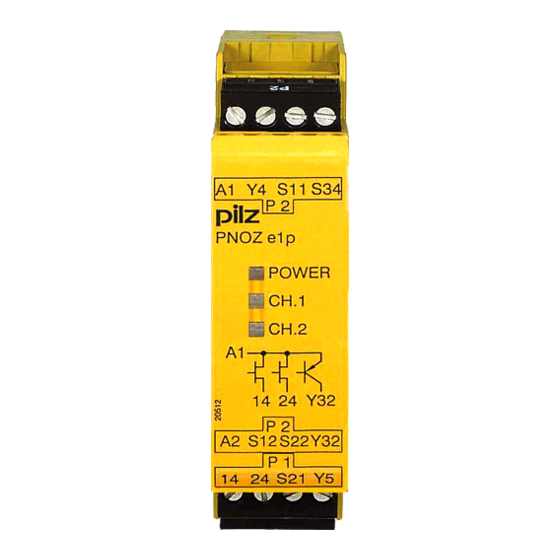
The safety device remains effective in the case of a component failure. The safety outputs are tested periodically using an off-test. Block diagram/terminal configuration Input Input Start Power Test Diag- Pulse nostic Output S11 S21 Operating Manual PNOZ e1p 21242-EN-13... -
Page 9: Function Description
The unit checks whether the input circuit is opened and then closed when supply voltage is applied. Increase in the number of available contacts by connecting contact expandsion modules or external contactors/relays. Operating Manual PNOZ e1p 21242-EN-13... -
Page 10: Selecting Sensors
When installed vertically: Secure the unit by using a fixing element (e.g. retaining bracket or end angle). NOTICE If you are connecting several units logically, please note the guidelines in the section entitled Logic connection between several units [ 14]. Operating Manual PNOZ e1p | 10 21242-EN-13... -
Page 11: Wiring
(on the input circuit) does not overload the proximity switch. The power supply must comply with the regulations for extra low voltages with protective electrical separation (SELV, PELV) in accordance with VDE 0100, Part 410. Terminal Y5 is provided for Pilz-internal diagnostic purposes. Operating Manual PNOZ e1p | 11... -
Page 12: Preparing For Operation
Light guard or safety switch, 24 V DC detection of shorts across contacts via ESPE The E-STOP pushbutton and safety gate switch symbolise a trigger element with N/C / N/C combination. Operating Manual PNOZ e1p | 12 21242-EN-13... -
Page 13: Start Circuit
Start circuit without feedback loop with feedback loop monit- monitoring oring Monitored start E-STOP wiring Monitored start Safety gate without start-up test K1 and K2 symbolise the contacts of the external contactors Operating Manual PNOZ e1p | 13 21242-EN-13... -
Page 14: Logic Connection Between Several Units
PNOZ e1p Logic connection between several units From Version 3.0, safety outputs on the PNOZ e1p can be logically linked to the safety in- puts on other PNOZelog units. Units from the PNOZelog product range can be logically connected to each other and to units from the PNOZmulti product range. -
Page 15: Operation
Status indicators POWER Supply voltage is present, operating mode is detected. POWER Initialisation phase CH.1 There is a high signal at safety output 14. CH.2 There is a high signal at safety output 24. Operating Manual PNOZ e1p | 15 21242-EN-13... -
Page 16: Faults - Interference
The number of LED flashes corresponds to a digit in the error code. The error code can consist of up to 4 digits. The digits are separated by a longer period without flash- ing. The entire sequence is constantly repeated. INFORMATION Error code 0: 16 flashes Operating Manual PNOZ e1p | 16 21242-EN-13... - Page 17 LED CH.1 or CH.2 flashes 3 times, short Pause Once for one second Pause 3 times, for one second each Error code 1: LED CH.1 or CH.2 flashes 3 times, short Pause Once for one second Operating Manual PNOZ e1p | 17 21242-EN-13...
- Page 18 The table below shows the relationship between the number of flashes and the error code. The key to the error codes is described in the Error coding table. Number of flashes Decimal er- ror code Operating Manual PNOZ e1p | 18 21242-EN-13...
- Page 19 – 13x long – 3x short 1, 4 3x short – 1x long Operating mode changed during Check wiring for the operating mode – 4x long – 3x short operation and rectify fault Operating Manual PNOZ e1p | 19 21242-EN-13...
- Page 20 +24 VDC 2, 0, 3 3x short – 2x long <19.2 VDC Keep within the supply voltage range – 16x long – 3x long of 19.2 ... 30 VDC – 3x short Operating Manual PNOZ e1p | 20 21242-EN-13...
-
Page 21: Dimensions
24 V Current at Input circuit DC 5 mA 5 mA Start circuit DC 5 mA 5 mA Feedback loop DC 5 mA 5 mA Min. input resistance at power-on 3.780 Ohm 3.780 Ohm Operating Manual PNOZ e1p | 21 21242-EN-13... - Page 22 After power on With automatic start typ. 100 ms 100 ms With automatic start max. 180 ms 180 ms With monitored start typ. 180 ms 180 ms With monitored start max. 260 ms 260 ms Operating Manual PNOZ e1p | 22 21242-EN-13...
- Page 23 PPO UL 94 V0 PPO UL 94 V0 Front ABS UL 94 V0 ABS UL 94 V0 PPO UL 94 V0 PPO UL 94 V0 Connection type Screw terminal Spring-loaded terminal Mounting type plug-in plug-in Operating Manual PNOZ e1p | 23 21242-EN-13...
- Page 24 8 mm Dimensions Height 90,5 mm 94 mm Width 22,5 mm 22,5 mm Depth 121 mm 121 mm Weight 120 g 120 g Where standards are undated, the 2020-07 latest editions shall apply. Operating Manual PNOZ e1p | 24 21242-EN-13...
-
Page 25: Safety Characteristic Data
A safety function's SIL/PL values are not identical to the SIL/PL values of the units that are used and may be different. We recommend that you use the PAScal software tool to calculate the safety function's SIL/PL values. Operating Manual PNOZ e1p | 25 21242-EN-13... -
Page 26: Remove Plug-In Terminals
Product type Features Order no. Terminal block filter 1 Terminal block with filter for 3-10 kOhm load range 774195 Terminal block filter 2 Terminal block with filter for 10-30 kOhm load range 774196 Operating Manual PNOZ e1p | 26 21242-EN-13... - Page 27 This product/these products meet the requirements of the directive 2006/42/EC for ma- chinery of the European Parliament and of the Council. The complete EC Declaration of Conformity is available on the Internet at www.pilz.com/downloads. Authorised representative: Norbert Fröhlich, Pilz GmbH & Co. KG, Felix-Wankel-Str. 2, 73760 Ostfildern, Germany UKCA-Declaration of Conformity This product(s) complies with following UK legislation: Supply of Machinery (Safety) Regu- lation 2008.
- Page 28 We are represented internationally. Please refer to our homepage www.pilz.com for further details or contact our headquarters. Headquarters: Pilz GmbH & Co. KG, Felix-Wankel-Straße 2, 73760 Ostfildern, Germany Telephone: +49 711 3409-0, Telefax: +49 711 3409-133, E-Mail: info@pilz.com, Internet: www.pilz.com...
Need help?
Do you have a question about the PNOZ e1p and is the answer not in the manual?
Questions and answers