Table of Contents
Advertisement
Advertisement
Table of Contents

Related Manuals for Pilz PNOZ e3.1p


Summary of Contents for Pilz PNOZ e3.1p
- Page 1 PNOZ e3.1p Safety relays Operating Manual-21240-EN-09...
- Page 2 Preface This document is the original document. All rights to this documentation are reserved by Pilz GmbH & Co. KG. Copies may be made for the user's internal purposes. Suggestions and comments for improving this documenta- tion will be gratefully received.
-
Page 3: Table Of Contents
Feedback loop .......................... Logic connection between several units ................Logic input S35 and S36......................Examples ..........................Operation ..........................Status indicators ........................Faults – Interference ......................Dimensions in mm ......................... Technical details ........................Safety characteristic data ......................Operating Manual PNOZ e3.1p 21240-EN-09... - Page 4 Contents Remove plug-in terminals ..................... Order reference ........................Product ............................. Accessories ..........................Operating Manual PNOZ e3.1p 21240-EN-09...
-
Page 5: Introduction
PNOZ e3.1p Introduction Validity of documentation This documentation is valid for the product PNOZ e3.1p. It is valid until new documentation is published. This operating manual explains the function and operation, describes the installation and provides guidelines on how to connect the product. -
Page 6: Safety
Safety Intended use The safety relay PNOZ e3.1p provides a safety-related interruption of a safety circuit. The safety relay meets the requirements of EN 60947-5-1 and EN 60204-1 and may be used in applications with: the safety sensors PSEN 2.1p-10 and PSEN 2.1p-11 in safety circuits in accordance with EN 60947-5-3:2005, PDF-M... -
Page 7: Safety Regulations
Disposal In safety-related applications, please comply with the mission time T in the safety-related characteristic data. When decommissioning, please comply with local regulations regarding the disposal of electronic devices (e.g. Electrical and Electronic Equipment Act). Operating Manual PNOZ e3.1p 21240-EN-09... -
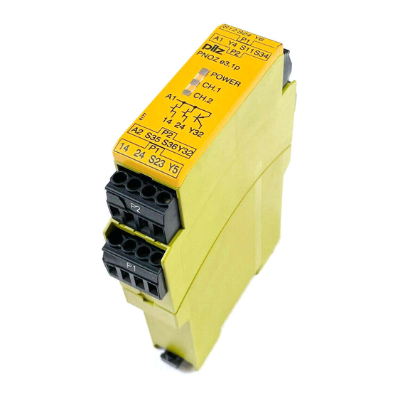
Page 8: Unit Features
The safety device remains effective in the case of a component failure. The safety outputs are tested periodically using an off-test. Block diagram/terminal configuration Feed- & Input Input Start back Power Test Diag- Pulse nostic Output S11 S23 Operating Manual PNOZ e3.1p 21240-EN-09... -
Page 9: Function Description
AND/OR connection The PNOZ e3.1p has two logic inputs S35 (OR) and S36 (AND) for logic connections between several units. Operating modes Dual-channel operation: Earth faults in the input circuit and shorts between the input cir- cuit contacts will be detected. -
Page 10: Installation
You must comply with the idling capacity at safety outputs 14 and 24 (see Technical details [ 25]). Do not connect undesignated terminals. Output Y32 is an auxiliary output, e.g. for communication with a PLC or text display. Operating Manual PNOZ e3.1p | 10 21240-EN-09... -
Page 11: Preparing For Operation
(on the input circuit) does not overload the proximity switch. The power supply must comply with the regulations for extra low voltages with protective electrical separation (SELV, PELV) in accordance with VDE 0100, Part 410. Terminal Y5 is provided for Pilz-internal diagnostic purposes. Preparing for operation Supply voltage... -
Page 12: Start Circuit
If you do not wish to connect any contacts to the feedback loop, Y6 must be connected to CAUTION! Do not connect the contacts from external contactors in series to the start circuit. Operating Manual PNOZ e3.1p | 12 21240-EN-09... -
Page 13: Logic Connection Between Several Units
Logically linking the units leads to delays when switching on and off (see on-delay and re- sponse time in the Technical details [ 25]). These are added up with each unit that is logically linked (Example 3 [ 18]). Operating Manual PNOZ e3.1p | 13 21240-EN-09... -
Page 14: Logic Input S35 And S36
The logic inputs are connected to each other as follows: Safety outputs Input circuit Logic inputs S35 and S36 from the PNOZ e3.1p enable additional PNOZelog or PNOZmulti units to be logically AND/OR connected. Input circuit Logic AND + OR... -
Page 15: Examples
In all the application examples, 2 loads may also be connected to the safety outputs. Example 1: Loads are connected to the safety outputs of Unit 1. In addition, a safety output is AND- linked to 4 other PNOZelog units via the logic input S36. Operating Manual PNOZ e3.1p | 15 21240-EN-09... - Page 16 PNOZ e3.1p Operating Manual PNOZ e3.1p | 16 21240-EN-09...
- Page 17 PNOZ e3.1p Example 2: Loads are connected to the safety outputs of Unit 1. In addition, a safety output is AND- linked to another PNOZelog unit via the logic input S36. Operating Manual PNOZ e3.1p | 17 21240-EN-09...
- Page 18 Unit 4. This means that Unit 4 and Unit 1 can set the outputs on Unit 2 and Unit 3 to low. A short circuit between +24 VDC and a safety output must be excluded! Operating Manual PNOZ e3.1p | 18 21240-EN-09...
-
Page 19: Operation
Status indicators POWER Supply voltage is present, operating mode is detected. POWER Initialisation phase CH.1 There is a high signal at safety output 14. CH.2 There is a high signal at safety output 24. Operating Manual PNOZ e3.1p | 19 21240-EN-09... -
Page 20: Faults - Interference
The number of LED flashes corresponds to a digit in the error code. The error code can consist of up to 4 digits. The digits are separated by a longer period without flash- ing. The entire sequence is constantly repeated. INFORMATION Error code 0: 16 flashes Operating Manual PNOZ e3.1p | 20 21240-EN-09... - Page 21 LED CH.1 or CH.2 flashes 3 times, short Pause Once for one second Pause 3 times, for one second each Error code 1: LED CH.1 or CH.2 flashes 3 times, short Pause Once for one second Operating Manual PNOZ e3.1p | 21 21240-EN-09...
- Page 22 The table below shows the relationship between the number of flashes and the error code. The key to the error codes is described in the Error coding table. Number of flashes Decimal er- ror code Operating Manual PNOZ e3.1p | 22 21240-EN-09...
- Page 23 – 13x long – 3x short 1, 4 3x short – 1x long Operating mode changed during Check wiring for the operating mode – 4x long – 3x short operation and rectify fault Operating Manual PNOZ e3.1p | 23 21240-EN-09...
- Page 24 +24 VDC 2, 0, 3 3x short – 2x long <19.2 VDC Keep within the supply voltage range – 16x long – 3x long of 19.2 ... 30 VDC – 3x short Operating Manual PNOZ e3.1p | 24 21240-EN-09...
-
Page 25: Dimensions In Mm
24 V 24 V Current at Input circuit DC 5 mA 5 mA Start circuit DC 5 mA 5 mA Feedback loop DC 5 mA 5 mA Logic input 5 mA 5 mA Operating Manual PNOZ e3.1p | 25 21240-EN-09... - Page 26 180 ms 180 ms With monitored start typ. 180 ms 180 ms With monitored start max. 260 ms 260 ms Logic inputs typ. 120 ms 120 ms Logic inputs max. 200 ms 200 ms Operating Manual PNOZ e3.1p | 26 21240-EN-09...
- Page 27 PPO UL 94 V0 PPO UL 94 V0 Front ABS UL 94 V0 ABS UL 94 V0 PPO UL 94 V0 PPO UL 94 V0 Connection type Screw terminal Spring-loaded terminal Mounting type plug-in plug-in Operating Manual PNOZ e3.1p | 27 21240-EN-09...
- Page 28 8 mm Dimensions Height 94 mm 101 mm Width 22,5 mm 22,5 mm Depth 121 mm 121 mm Weight 130 g 130 g Where standards are undated, the 2020-07 latest editions shall apply. Operating Manual PNOZ e3.1p | 28 21240-EN-09...
-
Page 29: Safety Characteristic Data
A safety function's SIL/PL values are not identical to the SIL/PL values of the units that are used and may be different. We recommend that you use the PAScal software tool to calculate the safety function's SIL/PL values. Operating Manual PNOZ e3.1p | 29 21240-EN-09... - Page 30 Product type Features Order no. Terminal block filter 1 Terminal block with filter for 3-10 kOhm load range 774195 Terminal block filter 2 Terminal block with filter for 10-30 kOhm load range 774196 Operating Manual PNOZ e3.1p | 30 21240-EN-09...
- Page 31 We are represented internationally. Please refer to our homepage www.pilz.com for further details or contact our headquarters. Headquarters: Pilz GmbH & Co. KG, Felix-Wankel-Straße 2, 73760 Ostfildern, Germany Telephone: +49 711 3409-0, Telefax: +49 711 3409-133, E-Mail: info@pilz.com, Internet: www.pilz.com...
Need help?
Do you have a question about the PNOZ e3.1p and is the answer not in the manual?
Questions and answers