Advertisement
Quick Links
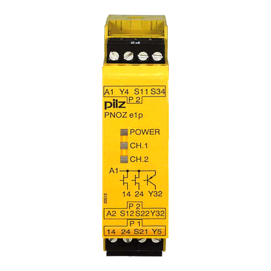
21 242-05
PNOZ e1p
Sicherheitsschaltgerät PNOZ e1p
Das Sicherheitsschaltgerät PNOZ e1p dient
dem sicherheitsgerichteten Unterbrechen
eines Sicherheitsstromkreises. Das Gerät
erfüllt Forderungen der EN 954-1 bis
Kategorie 4.
Das Gerät ist bestimmt für den Einsatz in:
• NOT-AUS-Einrichtungen
• Sicherheitsstromkreisen nach VDE 0113-1
und EN 60204-1 (z. B. bei beweglichen
Verdeckungen)
Wichtige Daten für Projektierung und
Anwendung finden Sie auch im technischen
Katalog PNOZelog.
Zu Ihrer Sicherheit
Das Sicherheitsschaltgerät PNOZ e1p erfüllt
alle notwendigen Bedingungen für einen
sicheren Betrieb.
Beachten Sie jedoch nachfolgend aufge-
führte Sicherheitsbestimmungen:
• Installieren und nehmen Sie das Gerät nur
dann in Betrieb, wenn Sie diese Betriebs-
anleitung gelesen und verstanden haben
und Sie mit den geltenden Vorschriften
über Arbeitssicherheit und Unfallverhütung
vertraut sind.
• Verwenden Sie das Gerät nur gemäß
seiner Bestimmung. Beachten Sie dazu
auch die Werte im Abschnitt "Technische
Daten".
• Halten Sie beim Transport, bei der
Lagerung und im Betrieb die Bedingungen
ein, wie sie unter "Technische Daten"
angegeben sind.
• Öffnen Sie nicht das Gehäuse und
nehmen Sie auch keine eigenmächtigen
Umbauten vor.
• Schalten Sie bei Wartungsarbeiten (z. B.
beim Austausch von Schützen) unbedingt
die Versorgungsspannung ab oder öffnen
Sie den Eingangskreis (z. B. NOT-AUS-
Taster betätigen), sonst kann das Gerät
bei Verdrahtungsfehlern unerwartet
einschalten.
Beachten Sie unbedingt die Warnhinweise in
den anderen Abschnitten dieser Anleitung.
Diese Hinweise sind optisch durch Symbole
hervorgehoben.
Wichtig: Beachten Sie die Sicher-
heitsbestimmungen, sonst erlischt
jegliche Gewährleistung.
Safety Relay PNOZ e1p
The safety relay PNOZ e1p is used for the
safety-related interruption of a safety circuit.
The unit meets requirements of EN 954-1 up
to category 4.
The unit is intended for use in:
• Emergency stop circuits
• Safety circuits to VDE 0113-1 and
EN 60204-1 (e.g. with moveable guards)
Important data for project planning and
application can also be found in the
PNOZelog technical catalogue.
For your safety
The safety relay PNOZ e1p meets all the
necessary conditions for safe operation.
However, please note the following safety
regulations:
• Only install and commission the unit if you
have read and understood these
instructions and are familiar with both
these instructions and the current
regulations for health and safety at work
and accident prevention.
• Only use the unit in accordance with its
intended purpose. Please also take note of
the values in the "Technical details"
section.
• Transport, storage and operating
conditions should all conform to the
standards as stated under "Technical
details".
• Do not open the housing or undertake any
unauthorised modifications.
• Please make sure you shut down the
supply voltage, or open the input circuit
(e.g. operate the E-STOP button) when
performing maintenance work (e.g. when
replacing contactors). In case of a wiring
error, the device might switch on
unexpectedly.
You must take note of the warnings given in
other sections of these operating instructions.
These are highlighted visually through the
use of symbols.
Notice: Failure to keep to these safety
regulations will render all warranty
invalid.
- 1 -
Bloc logique de sécurité PNOZ e1p
Le bloc logique de sécurité PNOZ e1p
assure de façon sûre l'ouverture d'un circuit
de sécurité. L'appareil satisfait aux exigences
de l'EN 954-1 jusqu'en catégorie 4.
L'appareil est spécialement conçu pour :
• les circuits d'arrêt d'urgence
• les circuits de sécurité selon VDE 0113-1
et EN 60204-1 (par ex., protecteurs
mobiles)
Vous trouverez également des données
importantes pour la configuration projet et
l'utilisation dans le Catalogue technique
PNOZelog.
Pour votre sécurité
Le bloc logique de sécurité PNOZ e1p
satisfait à toutes les conditions nécessaires
pour un fonctionnement sécuritaire.
Toutefois, vous êtes tenu de respecter les
prescriptions de sécurité suivantes :
• Vous n'installerez l'appareil et ne le
mettrez en service qu'après avoir lu et
compris le présent manuel d'utilisation et
que si vous êtes familier avec les prescrip-
tions en vigueur sur la sécurité du travail et
la prévention d'accidents.
• N'utilisez l'appareil que conformément à sa
définiton. A ce sujet, respectez les valeurs
indiquées dans les "Caractéristiques
techniques".
• Pour le transport, le stockage et
l'utilisation, respectez les exigences des
normes specifiées (voir „Caractéristiques
techniques").
• N'ouvrez pas le boîtier et n'effectuez pas
de modifications non autorisées.
• En cas de travaux de maintenance (par
ex. remplacement des contacteurs) coupez
impérativement la tension d'alimentation ou
ouvrez le circuit d'entrée (action sur le BP
d'arrêt d'urgence), sinon un réarmement
inopiné du relais est possible en cas
d'erreur de câblage.
Respectez impérativement les avertissements
dans les autres paragraphes du présent
manuel d'utilisation. Ces avertissements sont
signalés par des symboles visuels.
Important : Respectez les consignes
de sécurité, sinon la garantie devient
caduque.
Advertisement

Subscribe to Our Youtube Channel
Related Manuals for Pilz PNOZ e1p


Summary of Contents for Pilz PNOZ e1p
- Page 1 Safety Relay PNOZ e1p Bloc logique de sécurité PNOZ e1p Das Sicherheitsschaltgerät PNOZ e1p dient The safety relay PNOZ e1p is used for the Le bloc logique de sécurité PNOZ e1p dem sicherheitsgerichteten Unterbrechen safety-related interruption of a safety circuit.
- Page 2 Gerätebeschreibung Description Description de l’appareil Sicherheitseigenschaften: Safety features Propriétés de sécurité Das Sicherheitsschaltgerät erfüllt folgende The safety relay fulfils the following safety Le bloc logique de sécurité satisfait aux Sicherheitsanforderungen: requirements: exigences de sécurité suivantes : • Die Schaltung ist redundant mit Selbst- •...
- Page 3 • Querschlusserkennung wird durch • Start-up test prevents an automatic • La détection des court-circuits est rendue Taktung der Eingangskreise ermöglicht. restart when power is restored following a possible par test impulsionnel des circuits Diese Betriebsart wird beim Start auto- voltage loss.
- Page 4 • Der Ausgang Y32 ist ein Hilfsausgang with a PLC or display. afficheur. z. B. für die Kommunikation mit einer SPS • The PNOZ e1p can only be linked from • Le couplage de PNOZ e1p n’est permis oder einer Anzeige. version 3.0.
- Page 5 • Stellen Sie die Starteigenschaften durch • Set the reset features through the wiring of • Déterminez le type de réarmement par Verdrahten des Startkreises ein. the reset circuit. câblage du circuit de réarmement. Eingangskreis Automatischer Start ohne Rückführkreis Automatischer Start mit Rückführkreis Input circuit Automatic reset without feedback loop Automatic reset with feedback loop...
-
Page 6: Betrieb
Betrieb Operation Fonctionnement Beim Start erkennt das Gerät die eingestellte The unit detects the set operating mode on Au réarmement, l’appareil identifie le mode Betriebsart. In der dafür benötigten Zeit blinkt start-up. During this time the “POWER” LED de fonctionnement prédéfini. Pendant la die LED "POWER". - Page 7 Anschlussbeispiel: Connection example: Exemple de raccordement : zweikanalige NOT-AUS-Beschaltung, dual-channel E-STOP wiring, Arrêt d’urgence en 2 canaux, überwachter Start, monitored reset, detection of shorts réarmement manuel auto-contrôlé, Querschlusserkennung across contacts détection des courts-circuits Anschlussbeispiel: Connection example: Exemple de raccordement : zweikanalige Schutztüransteuerung, dual-channel safety gate controls, Surveillance de protecteurs avec 2...
-
Page 8: Remove Plug-In Terminals
Steckbare Klemmen abziehen Remove plug-in terminals Démonter les borniers Schraubendreher in Gehäuseaussparung Insert screwdriver into the cut-out of the débrochables hinter der Klemme ansetzen und Klemme housing behind the terminal and lever the Placer un tournevis derrière les bornes et heraushebeln. - Page 9 Zeiten Times Temps Überbrückung bei Max. supply interruption Tenue aux micro-coupures Spannungseinbrüchen before de-energisation max. 20 ms Anzugsverzögerung Delay-on energisation Temps de réarmement Überwachter Start Monitored reset Réarmement auto-contrôlé max. 260 ms, typ.180 ms Automatischer Start Automatic reset Réarmement automatique max.
- Page 10 Dimensions en mm (") Abmessungen in mm (") Dimensions in mm (") Gehäuse mit steckbaren Käfigzugfederklemmen/ Gehäuse mit steckbaren Schraubklemmen/ Housing with plug-in cage clamp terminals/ Housing with plug-in screw terminals/ Boîtier avec borniers débrochables à ressort Boîtier avec borniers débrochables à vis Anschlussbelegung Connector pin assignment Affectation des raccords...
- Page 11 Notizen Notes Notes - 11 -...
- Page 12 0224 2360180, Fax: 0224 2360184, E-Mail: pilz.tr@pilz.de Pilz Automation Safety L.P ., 734 354-0272, Fax: 734 354-3355, E-Mail: info@pilzusa.com www.pilz.com Pilz GmbH & Co. KG, Sichere Automation, Felix-Wankel-Straße 2, 73760 Ostfildern, Deutschland, +49 711 3409-0, Fax: +49 711 3409-133, E-Mail: pilz.gmbh@pilz.de - 12 -...
Need help?
Do you have a question about the PNOZ e1p and is the answer not in the manual?
Questions and answers