Table of Contents
Advertisement
Advertisement
Table of Contents

Related Manuals for Pilz PNOZ e2.2p


Summary of Contents for Pilz PNOZ e2.2p
- Page 1 PNOZ e2.2p Safety relays Operating Manual-21360-EN-06...
- Page 2 Preface This document is a translation of the original document. All rights to this documentation are reserved by Pilz GmbH & Co. KG. Copies may be made for internal purposes. Suggestions and comments for improving this documentation will be gratefully received.
-
Page 3: Table Of Contents
Wiring Preparing for operation Supply voltage Input circuit Feedback loop Logic connection between several units Logic inputs S35 and S36 Examples Operation Status indicators Faults - malfunctions Dimensions in mm Technical details Safety characteristic data Operating Manual PNOZ e2.2p 21360-EN-06... - Page 4 Contents Remove plug-in terminals Order reference Product Accessories Operating Manual PNOZ e2.2p 21360-EN-06...
-
Page 5: Introduction
PNOZ e2.2p Introduction Validity of documentation This documentation is valid for the product PNOZ e2.2p. It is valid until new documentation is published. This operating manual explains the function and operation, describes the installation and provides guidelines on how to connect the product. -
Page 6: Safety
Safety Intended use The two-hand control device PNOZ e2.2p meets the requirements of EN 574 Type III A. CAUTION! The two-hand control device PNOZ e2.2p may not be used on press con- trollers. For these we recommend the PNOZ e2.1p. It is only suitable for use where the risk analysis has established a low level of risk (e.g. -
Page 7: Safety Regulations
In safety-related applications, please comply with the mission time T in the safety-re- lated characteristic data. When decommissioning, please comply with local regulations regarding the disposal of electronic devices (e.g. Electrical and Electronic Equipment Act). Operating Manual PNOZ e2.2p 21360-EN-06... -
Page 8: Unit Features
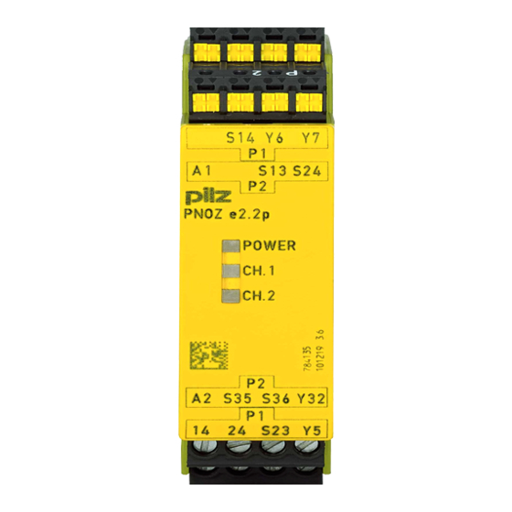
The safety device remains effective in the case of a component failure. The safety outputs are tested periodically using an off-test. Block diagram/terminal configuration Feed- & Input Input back Power Test Diag- Pulse nostic Output S13 S23 Operating Manual PNOZ e2.2p 21360-EN-06... -
Page 9: Function Description
AND/OR connection The PNOZ e2.2p has two logic inputs S35 (OR) and S36 (AND) for logic connections between several units. Operating modes Automatic start: Unit is active once the input circuit has been closed within the simultan- eity period. -
Page 10: Installation
The unit and the input circuits must always be supplied by a single power supply. The connection cables between the PNOZ e2.2p and the pushbuttons should not be laid directly next to power cables, otherwise inductive and capacitive interference coup- ling can result. -
Page 11: Preparing For Operation
The power supply must comply with the regulations for extra low voltages with protect- ive electrical separation (SELV, PELV) in accordance with VDE 0100, Part 410. Ensure the wiring and EMC requirements of EN 60204-1 are met. Terminal Y5 is provided for Pilz-internal diagnostic purposes. Preparing for operation Supply voltage... -
Page 12: Feedback Loop
If you do not wish to connect any contacts to the feedback loop, bridge the terminals as described in the table below. OR/no AND + OR/AND logic connection logic connection without feedback loop monit- oring with feedback loop monitor- Operating Manual PNOZ e2.2p 21360-EN-06... -
Page 13: Logic Connection Between Several Units
A valid signal at the OR input of a PNOZelog unit mutes its safety function and can lead to the most serious injuries and death. – Before using the OR function, carry out a risk analysis and use other measures to establish a safe condition. Operating Manual PNOZ e2.2p 21360-EN-06... -
Page 14: Logic Inputs S35 And S36
Logic inputs S35 and S36 Logic inputs S35 and S36 from the PNOZ e2.2p enable additional PNOZelog or PNOZmulti units to be logically AND/OR connected. Logic AND + OR connec-... - Page 15 PNOZ e2.2p Example 1: Loads are connected to the safety outputs of Unit 1. In addition, a safety output is AND- linked to 4 other PNOZelog units via the logic input S36. Operating Manual PNOZ e2.2p 21360-EN-06...
- Page 16 PNOZ e2.2p Example 2: Loads are connected to the safety outputs of Unit 1. In addition, a safety output is AND- linked to another PNOZelog unit via the logic input S36. Operating Manual PNOZ e2.2p 21360-EN-06...
- Page 17 Unit 4. This means that Unit 4 and Unit 1 can set the outputs on Unit 2 and Unit 3 to low. A short circuit between +24 VDC and a safety output must be excluded! Operating Manual PNOZ e2.2p 21360-EN-06...
- Page 18 Unit 3. If Unit 2 sends a high signal to the OR input on Unit 3, a high signal will be present at the outputs on Unit 3, irrespective of the status of its input circuit. Operating Manual PNOZ e2.2p 21360-EN-06...
-
Page 19: Operation
LED flashes Status indicators POWER Supply voltage is present, operating mode is detected. POWER Initialisation phase CH.1 There is a high signal at safety output 14. CH.2 There is a high signal at safety output 24. Operating Manual PNOZ e2.2p 21360-EN-06... -
Page 20: Faults - Malfunctions
The number of LED flashes corresponds to a digit in the error code. The error code can consist of up to 4 digits. The digits are separated by a longer period without flashing. The entire sequence is constantly repeated. INFORMATION Error code 0: 16 flashes Operating Manual PNOZ e2.2p 21360-EN-06... - Page 21 Examples Error code 1, 3: The Fault LED flashes 3 times, short Pause Once for one second Pause 3 times, for one second each 3 times, short Operating Manual PNOZ e2.2p 21360-EN-06...
- Page 22 The table below shows the relationship between the number of flashes and the error code. The key to the error codes is described in the Error coding table. Number of flashes 10 11 12 13 14 15 16 Decimal error code 10 11 12 13 14 15 0 Operating Manual PNOZ e2.2p 21360-EN-06...
- Page 23 3x short – 1x long – 13x long – 3x short 1, 4 3x short – 1x long Operating mode changed during Check wiring for the operating mode – 4x long – 3x short operation and rectify fault Operating Manual PNOZ e2.2p 21360-EN-06...
- Page 24 – 3x short puts and +24 VDC 2, 0, 3 3x short – 2x long <19.2 VDC Keep within the supply voltage range – 16x long – 3x long of 19.2 ... 30 VDC – 3x short Operating Manual PNOZ e2.2p 21360-EN-06...
-
Page 25: Dimensions In Mm
Feedback loop DC 24 V 24 V Logic input 24 V 24 V Current at Input circuit DC 5 mA 5 mA Feedback loop DC 5 mA 5 mA Logic input 5 mA 5 mA Operating Manual PNOZ e2.2p 21360-EN-06... - Page 26 Maximum time of feedback loop monitoring 150 ms 150 ms Supply interruption before de-ener- gisation 20 ms 20 ms Simultaneity, channel 1 and 2 max. 500 ms 500 ms Environmental data 774135 784135 Climatic suitability EN 60068-2-78 EN 60068-2-78 Operating Manual PNOZ e2.2p 21360-EN-06...
- Page 27 0,2 - 1,5 mm², 24 - 16 AWG – Torque setting with screw terminals 0,5 Nm – Conductor cross section with spring-loaded terminals: Flexible with/without crimp connector – 0,2 - 1,5 mm², 24 - 16 AWG Operating Manual PNOZ e2.2p 21360-EN-06...
-
Page 28: Safety Characteristic Data
A safety function's SIL/PL values are not identical to the SIL/PL values of the units that are used and may be different. We recommend that you use the PAScal software tool to calculate the safety function's SIL/PL values. Operating Manual PNOZ e2.2p 21360-EN-06... - Page 29 Product type Features Order no. Terminal block filter 1 Terminal block with filter for 3-10 kOhm load range 774 195 Terminal block filter 2 Terminal block with filter for 10-30 kOhm load range 774 196 Operating Manual PNOZ e2.2p 21360-EN-06...
- Page 30 Back cover Support Technical support is available from Pilz round the clock. Americas Australia Scandinavia Brazil +61 3 95600621 +45 74436332 +55 11 97569-2804 Spain Canada Europe +34 938497433 +1 888-315-PILZ (315-7459) Austria Switzerland Mexico +43 1 7986263-0 +41 62 88979-30...
Need help?
Do you have a question about the PNOZ e2.2p and is the answer not in the manual?
Questions and answers