Advertisement
Quick Links
MP05-00001
Revision: A0
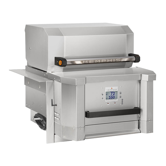
Memphis Elevate™ ITC 2
Model Number
MG01-06-001
Read all instructions before installing and using this appliance. Save these instructions for future reference.
A MAJOR CAUSE OF FIRES IS FAILURE TO
MAINTAIN REQUIRED CLEARANCES (AIR
SPACES) TO COMBUSTIBLE MATERIALS. IT
IS OF UTMOST IMPORTANCE THAT THIS
PRODUCT BE INSTALLED ONLY IN
ACCORDANCE WITH THESE INSTRUCTIONS.
Advertisement

Subscribe to Our Youtube Channel
Related Manuals for Memphis Elevate ITC 2


Summary of Contents for Memphis Elevate ITC 2
- Page 1 MP05-00001 Revision: A0 Memphis Elevate™ ITC 2 Model Number MG01-06-001 Read all instructions before installing and using this appliance. Save these instructions for future reference. A MAJOR CAUSE OF FIRES IS FAILURE TO MAINTAIN REQUIRED CLEARANCES (AIR SPACES) TO COMBUSTIBLE MATERIALS. IT...
-
Page 2: Table Of Contents
Table of Contents Warranty Registration Memphis Elevate™ Overview Clearance to Combustibles Electrical Installation Requirement Memphis Elevate Grill Head Parts List Assembly Instruction Memphis Wi-Fi Setup Guide Memphis Controller Diagram 11-12 Memphis Elevate Built-In Brackets Overview Cutout Dimensions Dimensions Parts List... -
Page 3: Warranty Registration
Scan for Warranty Registration Stop! Scan the QR Code above now to secure your grill warranty registration. Or register online at: https://memphisgrills.com/support-resources/warranty-registration/... -
Page 4: Memphis Elevate™ Overview
Memphis Elevate™ Overview MODEL NUMBER: MG11-06-001 DESCRIPTION: Built-In Bracket Assembly MODEL NUMBER: MG11-06-002 DESCRIPTION: Leg Assembly MODEL NUMBER: MG11-06-003 MODEL NUMBER: MG11-06-004 DESCRIPTION: Surround Assembly DESCRIPTION: Cabinet Assembly... - Page 5 18” [45.8 cm] 3/8” [1.0 cm) 30” [76.2 cm] Below are some guidelines to ensure safe operation of your Memphis Grill: • The grill is to be supported by the casters or fixed wheels and leveling feet depending on which assembly is purchased.
-
Page 6: Electrical Installation Requirement
Electrical Installation Dedicated Electrical Circuit with GFCI Protected Outlet A dedicated GFCI protected electrical circuit is REQUIRED for all Memphis Wood Fire Grills and controller systems. This circuit should be installed by a Certified Electrician. Although the Memphis Grill only uses about 5 amps of current during startup, any other equipment (refrigerator, pool pump, fountains, etc.) with a high current draw, consistently or intermittently, from the same... - Page 7 Grill Head Parts List Qty: Description/ Part No. Picture: OPTIONAL ACCESSORIES 1. Main Grates Qty: Description/ Part No. Picture: MA07-00003 A. Extended 2. Upper Grate 3 grates Grate Kit MD07-00008 per box MG33-01-004 3. Savorizer® VG4403 4. Direct Flame Insert VG4407 5.
- Page 8 Grill Head: Assembly Instructions Peel all plastic protective film prior to performing the assembly steps listed below. Refer to page 7 for item part numbers, descriptions, and quantities. Step 1) Remove the Savorizer (Part 3) and grates (Part 1 & Part 2) from inside the grill hood.
- Page 9 Grill Head: Assembly Instructions Step 3) Thread Wi-Fi antenna (Part 6) to Figure 3 bulkhead connector located on the Grill Head’s left panel side (Figure 3).
- Page 10 ON YOUR GRILL CONTROLLER: A Wi-Fi connection can be set up in minutes on your Memphis Wood Fire Grill. First power the grill ON by pressing the top left button on the controller, then from the home screen press the “MENU” button, then the “DOWN ARROW”, then the “WIFI”...
- Page 11 Memphis Control Diagram...
- Page 12 Pair is joined in the middle with terminals. Fuse holder accepts a 5 amp glass fuse. Holder black shrink wrap. Fuse holder is cylindrical and white plastic. CONTACT YOUR DEALER OR MEMPHIS GRILLS TECHNICAL SERVICE WITH ANY QUESTIONS. TECHNICAL SERVICE NUMBER: 1-888-883-2260...
-
Page 13: Parts List
Built-in Brackets Assembly MODEL NUMBER: MG11-06-001 1. Cutout Dimensions 2. Dimensions 3. Parts List 4. Assembly Instructions... -
Page 14: Cutout Dimensions
Built-In Cutout Dimensions NOTE: Dimensions are to the finished surfaces. Power Requirements Grill cavity surfaces are to be plumb and level to ensure a proper fit. 110/120VAC* supply required within 10 feet of the ITC. Top View Front View CUTOUT DIMENSIONS TOLERANCE 30 1/4”... - Page 15 Built-in Bracket Dimensions Additional Grill Dimensions Main Grate Area– 24.5 in X 17.7 in [62 cm X 45 cm] 428 in [2,761 cm Top Grate Area– 24.5 in X 6.125 in [63 cm X 16 cm] 150 in [968 cm *Middle Grate Kit Area–...
- Page 16 Built-In Brackets Parts List Qty: Qty: Description/ Part No. Description/ Part No. Picture: Picture: 9. M6 Lock Washer 1. Rear Mounting MH02-00002 Bracket BG8001 2. Right Mounting Bracket MA01-00013 3. Left Mounting Bracket TOOLS REQUIRED MA01-00014 10mm Open-end Wrench, Socket or •...
- Page 17 Built-In Brackets: Assembly Instructions Peel all plastic protective film off prior to performing the assembly steps listed below. Refer to page 16 for item part numbers, descriptions, and quantities. Step 1) Attach right mounting bracket (Part 2) onto the right side of the grill using 6 screws (Part 6) (See Figure 1).
- Page 18 Built-In Brackets: Assembly Instructions Step 3) Attach rear mounting bracket (Part 1) Figure 3 onto the side brackets using 2 screws (Part 8) (See Figure 3). Step 4) Attach lower mounting bracket (Part Figure 4 4) onto the bottom of the grill using 2 screws (Part 7) and 2 washers (Part 9) (See Figure Step 5) Attach front lower caps (Part 5) onto Figure 5...
- Page 19 Built-In Brackets: Assembly Instructions Step 6) With two people, lift the grill onto the island countertop and slide into the island cutout (See Figure 6a & 6b). Ensure vent holes on mounting brackets remain unobstructed for proper air circulation (See Figure 6c).
-
Page 20: Dimensions
Leg Assembly MODEL NUMBER: MG11-06-002 1. Dimensions 2. Parts List 3. Assembly Instructions... -
Page 21: Dimensions
Leg Assembly Dimensions Additional Grill Dimensions Main Grate Area– 24.5 in X 17.7 in [62 cm X 45 cm] 428 in [2,761 cm Top Grate Area– 24.5 in X 6.125 in [63 cm X 16 cm] 150 in [968 cm *Middle Grate Kit Area–... - Page 22 Leg Assembly Parts List Qty: Qty: Description/ Part No. Description/ Part No. Picture: Picture: 9. Side Shelf Left 1. Front Leg Right MA06-00011 MA09-00013 2. Front Leg Left 10. Grill Handle MA09-00023 MD01-00035 3. Rear Leg Right 11. M6 Screw (SS MA09-00015 MH01-00021 12.
- Page 23 Leg Assembly: Assembly Instructions Peel all plastic protective film off prior to performing the assembly steps listed below. Refer to page 22 for item part numbers, descriptions, and quantities. Step 1) Attach bottom cross brace (Part 7) to Figure 1 front leg (Part 1) and front leg (Part 2) using 4 screws (Part 11) and 4 lock washers (Part 12) (See Figure 1).
- Page 24 Leg Assembly: Assembly Instructions Step 3) Lay grill on its back. Attach rear legs Figure 3a (Part 3 & Part 4) onto the grill using 4 screws (Part 11) and 4 lock washers (Part 12) (See Figure 3a). Slide and set the tab into the slot (See Figure 3b &...
- Page 25 Leg Assembly: Assembly Instructions Step 5) Attach the front leg assembly from From Step 2 Step 2 using 8 screws (Part 11) and 8 lock washers (Part 12) (See Figure 5a & 5b). Partially thread screws with lock washers onto the top holes, and then insert and position the leg braces before tightening (See Applies to Figure 5c).
- Page 26 Leg Assembly: Assembly Instructions Step 7) From the rear of the grill, attach the leg assembly onto the grill using 4 screws (Part 11) and 4 lock washers (Part 12) (See Figure 7). Assembly Figure 7 Step 8) Attach the left side shelf (Part 9) onto Figure 8a the left side of the grill using 4 screws (Part 11) and 4 lock washers (Part 12) (See...
- Page 27 Leg Assembly: Assembly Instructions Step 9) Attach grill handle (Part 10) onto the Figure 9 right side of the grill using 4 screws (Part 11) and 4 lock washers (Part 12) (See Figure 9).
- Page 28 Surround Assembly MODEL NUMBER: MG11-06-003 Scan this QR code to access the Surround Assembly or go https://memphisgrills.com/ support-resources/support- manuals/...
- Page 29 Cabinet Assembly MODEL NUMBER: MG11-06-004 Scan this QR code to access the Surround Assembly or go https://memphisgrills.com/ support-resources/support- manuals/...
- Page 30 Scan to access Product Manuals Attention! To access the latest Product Manuals, scan the QR Code above. Or visit our website at: https://memphisgrills.com/support-resources/support-manuals/...
Need help?
Do you have a question about the Elevate ITC 2 and is the answer not in the manual?
Questions and answers