Memphis Elite Built-In ITC 3 Manual
Intelliburn technology
Hide thumbs
Also See for Elite Built-In ITC 3:
- Quick start manual (2 pages) ,
- Quick start manual (4 pages) ,
- Owner's manual (38 pages)
Table of Contents
Advertisement
Quick Links
VG0893
Memphis Elite Built-In ITC 3
Read all instructions before installing and using this appliance
IntelliBurn Technology
Model Number
Built-In Grill Island Dimensions
Hardware Components
Grill Installation and Operation
Memphis WiFi Setup
Memphis Component Diagram
Memphis Fuse Diagram
Save these instructions for future reference
TM
VGB0002S
3
4
5-9
10
11
12
13
Revision: A1
Advertisement
Table of Contents

Related Manuals for Memphis Elite Built-In ITC 3


Summary of Contents for Memphis Elite Built-In ITC 3
- Page 1 VG0893 Revision: A1 Memphis Elite Built-In ITC 3 IntelliBurn Technology Model Number VGB0002S Built-In Grill Island Dimensions Hardware Components Grill Installation and Operation Memphis WiFi Setup Memphis Component Diagram Memphis Fuse Diagram Read all instructions before installing and using this appliance...
-
Page 2: Clearance To Combustible Materials
Clearance to Combustible Materials Combustible Material is wood, dry wall, siding or any other material that has to ability to catch fire. Built-in structures constructed of wood or other combustible materials may require the use of the OPTIONAL Built-In Heat Shield Kit to maintain the required clearance to combustible materials. The grill may be supported by either the three support brackets, or the four leveling feet. -
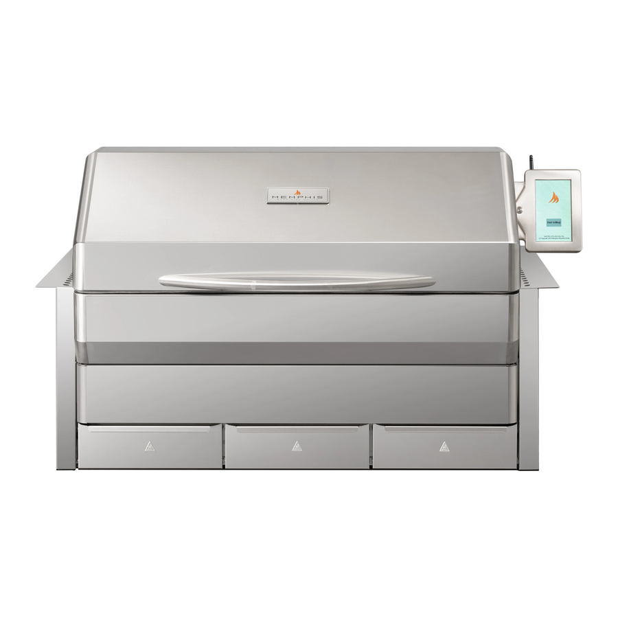
Page 3: Front View
Built-In Cutout Dimensions Power Requirements NOTE: Dimensions are to the finished surfaces. 110/120VAC* supply required within 10 feet Grill cavity surfaces are to be plumb and level of the ITC. Power cable located at the back to ensure a proper fit. right of the grill. -
Page 4: Hardware Components
Hardware Components Qty: Description/ Part No. Qty: Picture: Description/ Part No. Picture: 13. Left Mounting Bracket 1. VG0002 Grate VG0803 2. Savorizer 14. Right Mounting Bracket VG0802 VGE4403 3. Direct Flame Insert VG4407 15. Right Mounting Bracket VGE0801 4. Genie Tool VG1595 OPTIONAL 5. - Page 5 A dedicated GFCI protected electrical circuit is required for all Memphis Wood Fire Grills and controller systems. This circuit should be installed by a Certified Electrician. Although the Memphis Grill only uses about 2 amps of current during startup, any other equipment (refrigerator, pool pump, fountains, ect.) that have high current draw, consistently or intermittently, from the same electrical circuit can cause potential issues and/ or interruptions with the performance of the grill.
- Page 6 Installation Step 1: Unpacking Grill requires (2) two people for safe assembly Please note that during shipping some movement may have taken place, so a complete visual inspection is required. Be sure to inspect entire grill after removing the protective shipping carton. Report any damage to your local dealer immediately.
- Page 7 Installation Step 3: Brackets Follow the assembly steps listed below, prior to installation of the unit. The Unit can be supported by either the support brackets (items 13, 14, and 15) or by the four leveling feet (item 10). Refer to page 4 for item part numbers, descriptions, and quantities.
- Page 8 Installation Step 4: Grill Mounting 12. Place the unit into the island and position it to the desired depth. Ensure that the vent holes in the Mounting Holes support brackets are unobstructed for properly air circulation. 13. Locate the two mounting holes found in the back of the left and right support brackets (Items 13 and 14), and mark the hole locations onto the island’s countertop.
- Page 9 Installation Step 5: Final Assembly Refer to page 4 for item part numbers, descriptions, and quantities. 19. Inset the three ash/grease drawers back into the unit. 20. Place Savorizer (item 2) onto the left and right lower brackets found inside the unit. 21.
- Page 10 4. Follow the steps below on your Memphis 3 App. ON YOUR PHONE OR TABLET: (In Memphis 3 App) 5. Log into Memphis 3 App using your account email and password. 6. If no grill is connected, the BLE provisioning process will begin automatically.
- Page 11 Memphis Controller Diagram Part # Name Description VG1966 Auger Wiring Harness 5 pin connector from auger motor to the logic board VG1967 Blower Wiring Harness 4 pin connector from blower to the logic board VG1968 Display Wiring Harness 9 pin connector from the LCD display to the logic board...
- Page 12 Memphis Component Diagram Part # Name Description VG9501 Auger Motor This component rotates the auger to supply fuel into the burn pot VG1967 Blower This component pulls air from the lower cabinet and into the firebox for combustion VG1968 Used to display Grill information and change grill settings...
- Page 13 Memphis Fuse Diagram Power Cable (VG1969) Fuse VG9021– Fuse Glass 250VAC 5A 5 x 20 mm Logic Board Layout Antenna Jack MicroSD 4A SLO-BLO Fuse Connector 0.5A SLO-BLO Fuse 12A SLO-BLO Fuse...
Need help?
Do you have a question about the Elite Built-In ITC 3 and is the answer not in the manual?
Questions and answers