
Subscribe to Our Youtube Channel
Related Manuals for Orion 2030


Summary of Contents for Orion 2030
- Page 1 Orion Model 2030 Silica Analyzer Reference Manual © Copyright 1998 • All Rights Reserved • Printed in U.S.A. • Version: 1.0 •Part No.: 228620-001 Orion Research Inc. Rev. No. 001...
- Page 2 Contact your closest Orion Representative for more information: Orion Research Incorporated 500 Cummings Ctr Beverly, MA 01915 Telephone: 800-225-1480 Fax: 978-927-3932 Rev. No. 001...
-
Page 3: Table Of Contents
1.3 Colorimetric Analysis ................1-4 1.3.1 Dual Wavelength Colorimetry ..........1-5 A. Turbidity .................1-5 B. Second Reference Measurement ........1-6 C. Optical Fibers in Probe ............1-6 1.4 Major Components................1-7 1.4.1 Main Assemblies................1-7 1.4.2 Main Subsystems.................1-8 Orion Model 2030 Silica Analyzer Ref. Manual Rev. No. 001... - Page 4 P. Vent Valve Assembly............2-8 2.3.2 Optics Subsystem................2-8 A. Immersion Probe ..............2-9 B. Fiberoptic Bundle Assembly..........2-10 C. Detector Block Assembly .............2-11 D. Source Block Assembly ............2-13 2.3.3 Electronics..................2-13 2.3.4 Control Panel ................2-16 Rev. No. 001 Orion Model 2030 Silica Analyzer Ref. Manual...
- Page 5 4.3.1 Installing the Air Purge..............4-4 4.4 Performing Electrical Installation .............4-5 4.4.1 Installing AC Wiring..............4-5 4.4.2 Installing DC Wiring ..............4-10 A. Digital Input Lines..............4-10 B. Analog Output Lines ............4-11 C. RS-232C Wiring ..............4-11 Orion Model 2030 Silica Analyzer Ref. Manual Rev. No. 001...
- Page 6 6.7.1 Priming the Fluidics ..............6-12 6.7.2 Checking the Flow Rate.............6-13 6.7.3 Setting the Time and Date ............6-13 6.8 Restarting the Analyzer ...............6-13 6.8.1 Purging the Fluidics Lines............6-13 6.9 Describing Display Results..............6-14 Rev. No. 001 Orion Model 2030 Silica Analyzer Ref. Manual...
- Page 7 7.5.4 Set External Sample Device ............7-31 7.5.5 Set Flow Rate ................7-31 7.5.6 Modify Calibration Curve ............7-32 7.5.7 Set Offset Value................7-32 7.5.8 Set Gain Value ................7-33 7.5.9 Save Stream Information ............7-33 Orion Model 2030 Silica Analyzer Ref. Manual Rev. No. 001...
- Page 8 7.9 Save Unit Configuration..............7-56 7.10 Recover Unit Configuration..............7-56 7.11 Printing System Parameters..............7-57 7.11.1 Print Fluidics ................7-58 7.11.2 Print Calibration Setups............7-59 7.11.3 Print Methods ................7-59 7.11.4 Print Stream Information ............7-59 7.11.5 Print Sequences .................7-59 Rev. No. 001 Orion Model 2030 Silica Analyzer Ref. Manual...
- Page 9 7.17 Clearing Sections of Memory ............7-85 7.17.1 Clear Calibrations..............7-86 7.17.2 Clear Test Results..............7-86 7.17.3 Reset Calibration Setup............7-86 7.17.4 Reset Test Method ..............7-86 7.17.5 Reset Clock .................7-86 7.17.6 Reset Backup................7-86 7.17.7 Reset Memory................7-86 Orion Model 2030 Silica Analyzer Ref. Manual Rev. No. 001...
- Page 10 8.3 Shutdown and Restart Procedures ...........8-20 8.3.1 Performing Short-term Shutdown...........8-20 8.3.2 Restarting After Short-term Shutdown........8-20 8.3.3 Performing Extended Shutdown ..........8-20 A. Flushing the Standard Lines..........8-20 B. Cleaning Sample/Reaction Cell and Probe ......8-21 Rev. No. 001 Orion Model 2030 Silica Analyzer Ref. Manual...
- Page 11 C.3 General Faults ..................C-4 C.4 Level and Flow Alarms...............C-5 C.5 Hardware Alarms.................C-6 C.6 Other Alarms ..................C-8 Appendix D: Reports Appendix E: General Specifications Appendix F: Warning, Alarm, and Fault Messages Orion Model 2030 Silica Analyzer Ref. Manual Rev. No. 001...
- Page 13 Figure 2-9 Source Block Assembly ............2-13 Figure 2-10 Electronics Enclosure............2-14 Figure 3-1 Control Panel ................3-1 Figure 3-2 Orion Model 2030 Analyzer Menu Structure ....3-10 Figure 4-1 Installation Dimensions ............4-3 Figure 4-2 Power Supply Assembly.............4-6 Figure 4-3 Terminal Blocks on Main Board ........4-7 Figure 4-4 Terminal Blocks on Relay Board ........4-8...
- Page 14 Figure D-6 Digital Input/Output Information Printout ....D-5 Figure D-7 Parameters Information Printout........D-6 Figure D-8 System Status Information Printout.........D-6 Figure D-9 Stored Calibrations Information Printout .......D-7 Figure D-10 Alarm Information Printout..........D-7 Rev. No. 001 Orion Model 2030 Silica Analyzer Ref. Manual...
-
Page 15: Foreword
Step-by-step instructions guide you through all operating procedures and field programming. The Orion Model 2030 Series Analyzer has been designed to be very easy to use. Each analyzer in this family runs in a fully automated mode for rou- tine, day-to-day monitoring. The need for operator interaction is minimal. -
Page 16: Starting Out
Guide was shipped with your analyzer, and should be kept handy. Starting Out If you are placing your Orion Model 2030 Silica Analyzer in service for the first time, you must read through Chapter 4 (Installation) and Chap- ter 5 (Analyzer Startup). Follow the step-by-step instructions provided. - Page 17 Chapter 5, Analyzer Setup, furnishes procedures you need to help start up the Orion Model 2030 Silica Analyzer for the first time and bring it into on-line service. These procedures include: installing the startup kit; pre- paring solutions;...
-
Page 18: Design Change Notice
Manual Contents Foreword Appendix D, Reports, supplies examples of the various reports produced by the Orion Model 2030 Silica Analyzer. Appendix E, General Specifications, lists the general specifications of the Orion Model 2030 Silica Analyzer. Appendix F, Warning, Alarm, and Fault Messages, lists the types of warning, alarm, and fault messages and the appropriate corrective actions for each. -
Page 19: Typographic Conventions
Warnings indicate situations that could result in the injury of a human op- erator or bystander. Warnings are printed in all uppercase characters in boldface type, between two heavy horizontal rules, as in the following ex- ample: Orion Model 2030 Silica Analyzer Ref. Manual Rev. No. 001... -
Page 20: Cautions
Customer Service telephone number is (800) 225-1480. Technical assis- tance is also available from regional offices. This is Revision Number 002 of the Orion Model 2030 Series Reference Man- ual, Orion Document Number 228620-001, with an effective date of June 1998. -
Page 21: Chapter 1: Overview
Identification of the Orion Model 2030 Silica Analyzer’s three major assemblies and four subsystems and available options 1.1 Analyzer The Orion Model 2030 Silica Analyzer, illustrated in Figure 1-1, is a preci- sion industrial analyzer that performs silica analysis of one or more fluid Description sample streams using an established chemistry and dual-wavelength col- orimetry. -
Page 22: Features And Functions
The Orion Model 2030 Silica Analyzer is configured at the factory to accept commands via as RS-232C serial port. The RS-232C ports can be used to re- port to a printer, a remote computer, or other serial data communication device. -
Page 23: Analysis Cycle
Chapter 1: Overview 1.2 Features and Functions The Orion Model 2030 Silica Analyzer reports the results of each sample measurement and calibration on the control panel display and printer port, and it signals any alarm conditions that occur. Analysis results are re- ported over an isolated 4-20 mA current loop for driving a recorder or other analog device. -
Page 24: Colorimetric Analysis
Modern computer-aided spectrophotometric devices like the Orion Model 2030 Silica Analyzer measure the absorbance or optical density of a colored solution, usually in the visible region of the electromagnetic spec- trum: 400 to 850 nanometers (nm), specific to silica. They use optical band- pass filters to select one or more wavelengths of light in order to measure light absorption by a solution containing the silica of interest. -
Page 25: Dual Wavelength Colorimetry
The ef- fects of turbidity on single- and dual-wavelength methods are illustrated in Figure 1-2. Figure 1-2 Effects of Turbidity Orion Model 2030 Silica Analyzer Ref. Manual Rev. No. 001... -
Page 26: Second Reference Measurement
In the Orion Model 2030 Silica Analyzer, light passes through the sample twice. The light path begins at the incandescent source lamp. Incident light travels through the fiberoptic bundle to the probe window, then through the sample to a reflector. -
Page 27: Major Components
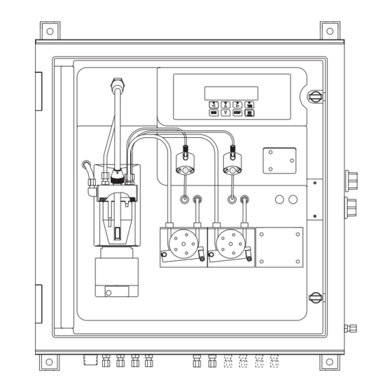
Chapter 1: Overview 1.4 Major Components 1.4 Major Figure 1-3 depicts a typical configuration for the Orion Model 2030 Silica Analyzer. Callouts identify key components; Chapter 2 describes these in Components more detail. 1.4.1 Main Physically, the Orion Model 2030 Silica Analyzer consists of these three... -
Page 28: Main Subsystems
1.5 Options Chapter 1: Overview 1.4.2 Main Functionally, the Orion Model 2030 Silica Analyzer is composed of these four main subsystems: Subsystems • Fluidics • Optics • Electronics • Control Panel For more information about these four main subsystems, see Chapter 2;... -
Page 29: General
2.1 General The Orion Model 2030 Silica Analyzer is housed in a single fiberglass en- closure that is designed to be mounted on a wall or similar sturdy vertical surface. The front cover of this enclosure is hinged along its left edge to permit operator access for routine functions. -
Page 30: Sample Manifold
The inside of the electronics enclosure should be accessed only by qualified service personnel. NOTE: When replacing the electronics cover, secure the captive screws firmly, using a torque wrench at a 100 oz/inch setting. Rev. No. 001 Orion Model 2030 Silica Analyzer Ref. Manual... -
Page 31: Main Functional Subsystems
Chapter 2: Hardware Description 2.3 Main Functional Subsystems 2.3 Main Functionally, the Orion Model 2030 Silica Analyzer consists of these four main subsystems: Functional Subsystems • Fluidics • Optics • Electronics • Control Panel The following subsections (2.3.1-2.3.4) furnish detailed descriptions of these subsystems. -
Page 32: Air Purge Fitting
) Caution: The length of Teflon tubing connected to the elbow fitting on the manifold (Figure 2-2) is set at the factory. Changing this length may affect analyzer operation adversely. Rev. No. 001 Orion Model 2030 Silica Analyzer Ref. Manual... -
Page 33: Inlet Fitting (Reagent)
The Pump Assembly (piston) works as a metering pump with positive- displacement piston action to add reagent to the sample. Compression tube fittings (1/8" Kynar) and Teflon tubing are used for fluid transport. Orion Model 2030 Silica Analyzer Ref. Manual Rev. No. 001... -
Page 34: Pump Assembly (Peristaltic)
The Reaction Cell Assembly holds the sample during analysis and calibra- tion. Figures 2-3 and 2-4 provide illustrations of this assembly. DRAIN FITTING IMMERSION PROBE SIPHON TUBE STIR BAR O-RING REACTION CELL Figure 2-3 Reaction Cell Assembly Rev. No. 001 Orion Model 2030 Silica Analyzer Ref. Manual... -
Page 35: Stirrer Assembly
Loosening the knurled screw on the bottom of the stirrer assem- bly allows the stirrer assembly to rotate counterclockwise and downward for removal and installation of the reaction cell. Orion Model 2030 Silica Analyzer Ref. Manual Rev. No. 001... -
Page 36: Vent Valve Assembly
This assembly operates at 24 VDC. It is made of a polypropylene body with Viton seals; 1/4" OD tubing is used for proper venting. 2.3.2 Optics The Orion Model 2030 Silica Analyzer optics subsystem, shown in Figure 2-5, consists of the following assemblies: Subsystem •... -
Page 37: Immersion Probe
Reflector Supports, which consist of three struts extending past the probe window on which the reflector mounts. Their open structure allows for adequate sample mixing and fluid flow through the light path. Orion Model 2030 Silica Analyzer Ref. Manual Rev. No. 001... -
Page 38: Fiberoptic Bundle Assembly
− Immersion Probe, which couples incident light into the sample solution and collects the transflected light returned through the sample. Rev. No. 001 Orion Model 2030 Silica Analyzer Ref. Manual 2-10... -
Page 39: Detector Block Assembly
100 oz/inch setting. Detector Block Assembly components include: − Temperature Sensor, which measures the temperature of the de- tector block (embedded inside the assembly). Orion Model 2030 Silica Analyzer Ref. Manual Rev. No. 001 2-11... - Page 40 − Detector, which measures the filtered light intensity after it passes through the sample (twice), converting it to an electrical signal that is amplified in the electronics. Rev. No. 001 Orion Model 2030 Silica Analyzer Ref. Manual 2-12...
-
Page 41: Source Block Assembly
Do not overtighten the nylon-tipped set screws. 2.3.3 Electronics Figure 2-10 provides an interior view of the electronics enclosure. Orion Model 2030 Silica Analyzer Ref. Manual Rev. No. 001 2-13... -
Page 42: Figure 2-10 Electronics Enclosure
INPUT 6 VALVE GROUND 3 THRU 6 INPUT 7 WATCH DOG ON/OFF INPUT 8 NOT ASSIGNED ENABLE SWITCH COM (-) VALVE DRIVER JUMPER COM (-) Figure 2-10 Electronics Enclosure Rev. No. 001 Orion Model 2030 Silica Analyzer Ref. Manual 2-14... - Page 43 Be sure that all external sources of power—those connected to relay contacts and analog outputs—are turned OFF or disconnected before you attempt to access circuitry in the electronics enclosure. Orion Model 2030 Silica Analyzer Ref. Manual Rev. No. 001 2-15...
-
Page 44: Control Panel
Two levels of menu access (and menu complexity) are available: (1) Routine and (2) Advanced. The Orion Model 2030 Silica Analyzer accepts commands and reports re- sults using a control panel mounted on the swing panel. The control panel consists of a display and a keypad;... -
Page 45: Chapter 3: Control Panel
• Understanding Sequences 3.1 Describing the The Orion Model 2030 Analyzer accepts commands and reports results us- ing a control panel mounted on the swing panel. The control panel con- Control Panel sists of a display and a keypad, and is shown in Figure 3-1. - Page 46 NOTE: You cannot damage the Orion Model 2030 Silica Analyzer by pressing the “wrong” key. While you may not achieve the result ex- pected and the outcome may cause a minor inconvenience, the ana- lyzer always recovers intact.
-
Page 47: Keypad
At the top menu level (reached when you press the [STOP] key), this key allows you to change the access level, using a passcode. Orion Model 2030 Silica Analyzer Ref. Manual Rev. No. 001... -
Page 48: Controlling The Analyzer
3.2 Controlling the Analyzer Chapter 3: Control Panel 3.2 Controlling The Orion Model 2030 Silica Analyzer can be operated three ways: (1) by an operator using the control panel, (2) by an external process controller the Analyzer via digital input lines, or (3) remotely through a serial (RS-232 or RS-485) data link. -
Page 49: Diagnostics
Detailed specifications for controlling the ana- lyzer in this way are given in section 4.4.2; the external control functions are referenced in Table 3-3. Orion Model 2030 Silica Analyzer Ref. Manual Rev. No. 001... -
Page 50: Explaining Analyzer Functions
3.3 Explaining Analyzer Functions Chapter 3: Control Panel 3.3 Explaining The Orion Model 2030 Silica Analyzer performs many of its functions in automated sequences, or cycles, as described in the following sections. Analyzer Functions 3.3 1 Analysis Cycle The steps listed below describe the sequence of events in a typical analysis. - Page 51 (that is, S, ST, STA, STAB, STABL). The number of letters displayed is a rough gauge of stability; that is, as more of the word appears, the ana- lyzer is establishing an increasingly stable reading. Orion Model 2030 Silica Analyzer Ref. Manual Rev. No. 001...
-
Page 52: Manual And Automatic Modes
The analyzer can switch between auto mode and manual mode under op- erator control from the control panel or under external control via the digi- tal input lines. Rev. No. 001 Orion Model 2030 Silica Analyzer Ref. Manual... -
Page 53: Run/Resume Function
When enabled in the auto blank method, the analyzer takes an absorption measurement during analysis after Reagent 2 is added, then uses the re- sult to correct the final concentration reported. Orion Model 2030 Silica Analyzer Ref. Manual Rev. No. 001... -
Page 54: Navigating Menus
Read this section if you are not familiar with the analyzer’s control panel and menu structure. Figure 3-2 depicts the software’s menu levels graphi- Menus cally. Figure 3-2 Orion Model 2030 Analyzer Menu Structure Rev. No. 001 Orion Model 2030 Silica Analyzer Ref. Manual 3-10... -
Page 55: Editing A Value
Chapter 3: Control Panel 3.4 Navigating Menus Consider the following main points in navigating the Orion Model 2030 Silica Analyzer’s various menus: • The [RUN] key always interrupts the current process and initiates the auto analysis mode, as long as the system is calibrated. In other words, the analyzer is always ready for routine operation. -
Page 56: Describing Sequences
3.5 Describing Sequences Chapter 3: Control Panel 3.5 Describing A sequence is a series of steps that are cyclically executed in a pre- determined fashion. The sequences defined in the Orion Model 2030 Silica Sequences Analyzer are as follows: •... -
Page 57: Chapter 4: Installation
Performing Electrical Installation This chapter specifies the steps you must take to properly install the Model 2030 Silica Analyzer at the site where it is to be used. Follow these instructions carefully to avoid damaging the analyzer and to assure its proper operation in routine service. -
Page 58: Preparing For Physical Installation
Connections to the power mains must be performed by a qualified electrician. NOTE: When replacing the electronics cover, secure the captive screws firmly, using a torque wrench at a 100 oz/inch setting. Rev. No. 001 Orion Model 2030 Silica Analyzer Ref. Manual... -
Page 59: Figure 4-1 Installation Dimensions
Chapter 4: Installation 4.2 Preparing for Physical Installation Figure 4-1 Installation Dimensions Orion Model 2030 Silica Analyzer Ref. Manual Rev. No. 001... -
Page 60: Mounting The Analyzer
4.3.1 Installing the The Model 2030 Silica Analyzer is equipped with an air purge fitting, which purges the electronics enclosure in case of corrosive gases being Air Purge present at the location of the analyzer. -
Page 61: Performing Electrical Installation
Route wiring for external controls to the main mother board appro- priate connectors as shown in Figure 4-2, and relay alarms to the relay board as shown in Figure 4-3, with reference to Table 4-2. Orion Model 2030 Silica Analyzer Ref. Manual Rev. No. 001... -
Page 62: Figure 4-2 Power Supply Assembly
PIN7 JMP TO PIN12 PIN8 +24V PIN9 NC PIN10 REMOVED PIN11 -12V PIN12 JMP TO PIN7 PIN13 +12V 100-240VAC 50/60HZ FUSES POWER NEUTRAL F3.15A250V GROUND POWER CONNECTIONS Figure 4-2 Power Supply Assembly Rev. No. 001 Orion Model 2030 Silica Analyzer Ref. Manual... -
Page 63: Figure 4-3 Terminal Blocks On Main Board
ANALOG INPUT LO (COM -) COM (-) CONTROL INPUT 2 INPUT 7 NOT ASSIGNED OPTIONAL (CONSULT FACTORY) INPUT 8 STROBE (ACTIVATE) COM (-) COM (-) Figure 4-3 Terminal Blocks on Main Board Orion Model 2030 Silica Analyzer Ref. Manual Rev. No. 001... -
Page 64: Figure 4-4 Terminal Blocks On Relay Board
AS NORMALLY OPEN OR NORMALLY CLOSED. * THESE OUTPUTS CORRESPOND TO OUTPUT#3 THRU 6 ON UNITS WITH A REV 5 OR EARLIER MAIN BOARD Figure 4-5 Optional Multiplexer Board Connections Rev. No. 001 Orion Model 2030 Silica Analyzer Ref. Manual... - Page 65 Two terminals per Relay 1 through 8 relay for Relay #8 * Relay #8 * * Note jumper configuration for N.O. (normally open) and N.C. (normally closed). Refer to Figure 4-4. Orion Model 2030 Silica Analyzer Ref. Manual Rev. No. 001...
-
Page 66: Installing Dc Wiring
DC wiring for digital input lines and for the analog outputs should be twisted pair, minimum #24 AWG. Wiring of the RS-232C interface uses a Wiring standard cable, which is typically supplied by Orion as part of the startup kit. Caution: Installing the DC wiring requires removing the electronics cover. -
Page 67: Analog Output Lines
The serial ports are configured for 9600 baud, eight-bit, no parity, one stop bit (8N1), no flow control transmissions operation by default. Orion Model 2030 Silica Analyzer Ref. Manual Rev. No. 001 4-11... -
Page 68: Figure 4-7 Connecting The Rs-232C Cable
232C port can be reconfigured as a DTE (Data Terminal Equipment) de- vice through use of an appropriate converter plug. Table 4-5 lists the pin- outs at the DB-9 (external) female connector. Figure 4-7 Connecting the RS-232C Cable Rev. No. 001 Orion Model 2030 Silica Analyzer Ref. Manual 4-12... - Page 69 Signal ground for both transmit and receive data. CTS (Clear to Output from analyzer to indicate that the Send) analyzer is ready to receive data. Used in hardware flow control. Orion Model 2030 Silica Analyzer Ref. Manual Rev. No. 001 4-13...
-
Page 71: Installing The Startup Kit
Startup Chapter 5 furnishes procedures you need to help start up the Orion Model 2030 Silica Analyzer for the first time and bring it into on-line service. Fol- low the procedures described in this section after completing all the instal- lation steps in Chapter 4. -
Page 72: Installing The Magnetic Stirrer
Place the magnetic stirrer into the cell, and screw the cell back onto the stirrer assembly. Reposition the stirrer assembly by rotating it back into position. Tighten the knurled fastener by hand. Rev. No. 001 Orion Model 2030 Silica Analyzer Ref. Manual... -
Page 73: Installing The Peristaltic Pump Tubing
Attach the shorter tubing connection to the barbed fitting on the swing panel. Flip the pump lever to secure the pump platen against the installed tubing, as shown in Figure 5-2. Orion Model 2030 Silica Analyzer Ref. Manual Rev. No. 001... -
Page 74: Figure 5-3 Tubing Paths
5.1 Installing the Startup Kit Chapter 5: Analyzer Startup SAMPLE REAGENT#3 REAGENT#2 PISTON PISTON PUMP PUMP FLUID TO DRAIN PERISTALTIC PUMP PERISTALTIC PUMP REAGENT#1 CAL STD Figure 5-3 Tubing Paths Rev. No. 001 Orion Model 2030 Silica Analyzer Ref. Manual... -
Page 76: Preparing Solutions
Reagent Check cycles. It is recommended that you install check valves (supplied by Orion Valves as part of the startup kit) on the tubing of reagents 2 & 3 as shown in Figure 5-5. -
Page 77: Connecting The Fluidics
Chapter 5: Analyzer Startup 5.3 Connecting the Fluidics 5.3 Connecting A functional description of Orion Model 2030 fluidics system is shown in Figure 2-1. the Fluidics Position all solution containers, each filled to the desired volume with the required reagent or calibration standard. -
Page 78: Powering Up The Analyzer
When the analyzer is turned on, it goes through a power up sequence which resets the hardware and refreshes the software configuration. The Orion Model 2030 Silica Analyzer is equipped with non-volatile random access memory (NVRAM) and electronically erasable/pro- grammable read-only memory (EEPROM), where the analyzer con- figuration is stored. -
Page 79: Priming The Fluidics
This message corresponds to the bootup screen for the Operator ac- cess level. The analyzer is now ready to prime the fluidics. NOTE: The Orion Model 2030 Silica Analyzer has various access levels that protect key operations from unauthorized use. It is shipped from the factory at the “Operator”... -
Page 80: Checking And Adjusting Sample Flow Rate
5.6 Checking and Adjusting Sample Flow Rate Chapter 5: Analyzer Startup 5.6 Checking and As shipped from the factory, the Orion Model 2030 Silica Analyzer is set up for an assumed sample-stream flow rate of 200 mL per minute. The ana- Adjusting Sample lyzer functions properly as long as the sample flow rate remains within ±... -
Page 81: Changing The Time And Date
5.7 Changing the The time and date can be modified through the “Prime Fluidics” function in the Operator menu. Please refer to Chapter 7 for details. Time and Date Orion Model 2030 Silica Analyzer Ref. Manual Rev. No. 001 5-11... -
Page 82: Calibrating For The First Time
Please refer to Chapter 6 for instructions on calibrating the Orion Model 2030 Silica Analyzer. It is best to run three (3) calibrations. This takes 20-45 minutes; a result displays and prints (if a printer is installed) as each cali- bration is completed. -
Page 83: Placing The Analyzer Into Service
Chapter 5: Analyzer Startup 5.9 Placing the Analyzer into Service 5.9 Placing the Your Orion Model 2030 Silica Analyzer is now ready for routine operation. To place the analyzer in routine service, press the control panel [RUN] Analyzer into key. For more information on the actual analysis sequence, refer to Chap- Service ter 3. - Page 85 Chapter 6: Routine Operation Chapter 6 describes the routine operation of the Orion Model 2030 Silica Analyzer. Routine operation is very straightforward, since the analyzer is designed to run automatically most of the time. Topics discussed in this chapter include: •...
-
Page 86: Accessing Routine Functions
Routine operation consists of the following functions: • Monitoring the Orion Model 2030 Silica Analyzer’s automatic opera- tion, checking to see if it is operating properly with no problems evi- dent, such as empty containers, fluid leaks, errors reported in the dis- play, etc. -
Page 87: Stopping The Analyzer
Perform the desired function. Re-start the analyzer. 6.2 Stopping the At any given time, the Orion Model 2030 Silica Analyzer might be active Analyzer (analyzing a sample stream or calibrating) or inactive (idle or in standby mode). If it is active, to stop it, you must either wait until the present opera- tion is completed or interrupt that operation. -
Page 88: Running A Calibration
6.5 Running a Calibration Chapter 6: Routine Operation 6.5 Running a Although the Orion Model 2030 Silica Analyzer is usually set up to cali- brate on a regular schedule, you may wish to execute a calibration cycle on Calibration command to assure that the analyzer is fully calibrated right now. This function runs a specified calibration setup without initiating the auto- matic mode. - Page 89 (Std2) is selected, if functions exactly like Cal on Std2. All alarms, repeat limits, and actions, etc. are enforced. NOTE: the 000.00 in the above prompt is replaced by the standard con- centration value supplied by the user. Orion Model 2030 Silica Analyzer Ref. Manual Rev. No. 001...
-
Page 90: Running A Grab Analysis
If you select the dual-point option, you must specify both standard con- centrations after specifying the Calibration Setup. The Orion Model 2030 Silica Analyzer runs the single-point procedure as described above, first on the low point (the standard with the lower concentration value), fol- lowed by the high point. - Page 91 If fluid is detected in any one of the aforementioned steps, the analyzer proceeds to do the 30-second siphon to capture the sample, add reagents, make measurements, etc. Orion Model 2030 Silica Analyzer Ref. Manual Rev. No. 001...
-
Page 92: Validating A Calibration Standard
6.5 Running a Calibration Chapter 6: Routine Operation 6.5.2 Validating a You can check the Orion Model 2030 Silica Analyzer’s calibration accuracy at any time using this function. Validation consists of running a single cali- Calibration Standard bration cycle and reporting the result in concentration. This reported re-... -
Page 93: Running An Analysis
Chapter 6: Routine Operation 6.6 Running an Analysis 6.6 Running an Although the Orion Model 2030 Silica Analyzer is usually set up to analyze sample streams on a regular schedule, you may wish to execute an analy- Analysis sis on command to obtain an immediate result. This function allows you to run multiple analyses on a sample without requiring that the automatic mode be initiated. -
Page 94: Selecting Standby Operation
For details on setting up the Standby Wash, please refer to Chapter 7. The Orion Model 2030 Silica Analyzer automatically goes into standby op- eration after half an hour (30 minutes) of inactivity when not in automatic operation. - Page 95 Chapter 6: Routine Operation 6.6 Running an Analysis NOTE: Do not attempt to access Orion Model 2030’s Technician Level menu if you are not authorized to do so. Obtain authorization first from the appropriate person at your facility, then learn the pass code before proceeding.
-
Page 96: Performing Startup Functions
You can now test for flow on each one of the sample streams on your analyzer as described in the next section. Rev. No. 001 Orion Model 2030 Silica Analyzer Ref. Manual 6-12... -
Page 97: Checking The Flow Rate
6.8.1 Purging the To purge the fluidics lines, you can use Hardware Test, Fluidics Control menu, or Priming the Fluidics under the Operator menu (see section Fluidics Lines 6.7.1). Orion Model 2030 Silica Analyzer Ref. Manual Rev. No. 001 6-13... -
Page 98: Describing Display Results
In this situation, you are back in the “Display Results” mode, and you can continue to review stored analy- ses, calibration, and alarms while the analysis is in progress. Rev. No. 001 Orion Model 2030 Silica Analyzer Ref. Manual 6-14... -
Page 99: Chapter 7: Advanced Operation
Chapter 7: Advanced Operation Chapter 7 details the advanced functions available to an authorized user of the Orion Model 2030 Silica Analyzer, functions that go beyond those typically encountered in routine operation (see Chapter 6). These func- tions fall into three categories: •... -
Page 100: Accessing Advanced Functions
NOTE: Do not attempt to access the analyzer’s Technician Level menu if you are not authorized to do so. Obtain authorization first from the ap- propriate person at your facility, and learn the pass code, before pro- ceeding. Rev. No. 001 Orion Model 2030 Silica Analyzer Ref. Manual... -
Page 101: Returning To The Operator Level
Standby Operation seals or pinching of the peristaltic pump tubing. When going into standby mode, the Orion Model 2030 Silica Analyzer may perform a standby wash if programmed to do so. 7.1.3 Saving and... -
Page 102: Defining A Calibration Setup
7.2 Defining a Calibration Setup Chapter 7: Advanced Operation 7.2 Defining a The Orion Model 2030 Silica Analyzer uses a two-point calibration tech- nique when calculating concentrations from a measured absorbance. Calibration Setup Each point associates a known concentration with a known absorbance. - Page 103 Chapter 7: Advanced Operation 7.2 Defining a Calibration Setup NOTE: When a new setup is being defined, the Orion Model 2030 Sil- ica Analyzer prompts you to confirm creation of the new calibration Setup through the following display: Defining New Setup.
-
Page 104: Set Calibration Standard Concentration
Warning Messages below. [STD1] Switch between displaying Std1 and Initially always [STD2] Std2 concentrations. shows the Std1 concentration. [EXIT] Exit to Set Cal Std Abs Rev. No. 001 Orion Model 2030 Silica Analyzer Ref. Manual... -
Page 105: Set Calibration Standard Absorbance
Std1 = 0.000 calibration Setup 01 are equal. ** Check S01 Conc ** The two standard absorbances for Std1 Abs = 0.000 calibration Setup 01 are equal. ** Check S01 Abs ** Orion Model 2030 Silica Analyzer Ref. Manual Rev. No. 001... -
Page 106: Set Calibration Device
7.2 Defining a Calibration Setup Chapter 7: Advanced Operation 7.2.3 Set Calibration There is only one calibration pump on the Orion Model 2030 Silica Ana- lyzer, which is typically used to pump deionized water. If additional stan- Device dards are needed during automatic operation, they must be delivered via a sample valve. -
Page 107: Set Calibration Type
Save & Continue (S+C): If the measured absorbance is outside the calibration repeat limit, the analyzer flags an error but stores the measured absorbance in the calibration Setup and uses it as a valid point in the calibration curve. Orion Model 2030 Silica Analyzer Ref. Manual Rev. No. 001... - Page 108 Ref Abs = 0.000 Are you sure ? To change the absolute reference value, answer [NO] to the above question and enter the appropriate value: ± 3.000 0.000 Ref Abs = +0.000 Rev. No. 001 Orion Model 2030 Silica Analyzer Ref. Manual 7-10...
-
Page 109: Save Calibration Setup
Change to M01 ? method to Method 01, which is always defined. If this is acceptable, press [YES], otherwise, the method must be assigned from the list of currently defined methods. Orion Model 2030 Silica Analyzer Ref. Manual Rev. No. 001 7-11... -
Page 110: Defining An Analysis Method
7.3 Defining an Analysis Method Chapter 7: Advanced Operation 7.3 Defining an The Orion Model 2030 Silica Analyzer runs a nine-step analysis sequence as discussed in Chapter 3. Information on how to run an analysis is stored Analysis Method in the Analysis Method. An Analysis Method consists of these parameters: •... -
Page 111: Set Cell Wash
NOTE: Always select a cell wash volume greater than 9-10 capture vol- umes. Cell Wash = 360 ml EXIT Orion Model 2030 Silica Analyzer Ref. Manual Rev. No. 001 7-13... - Page 112 40 - 130 mL 40 mL upon allocation and capture volume. Pre Wash Volume = 40 mL [CELL] Display cell wash information (see the table above for details). [EXIT] Exit to menu. Rev. No. 001 Orion Model 2030 Silica Analyzer Ref. Manual 7-14...
-
Page 113: Set Reagent Addition Sequence
Access the modify menu as shown in the next table. [EXIT] Exit to Set Blank Step. Upon pressing [EDIT], the following message displays: 1.5 mL of Rgt1 MODIFY EXIT Orion Model 2030 Silica Analyzer Ref. Manual Rev. No. 001 7-15... - Page 114 To define a new reagent addition sequence, you need to ADD a new step to the undefined sequence. The analyzer does not let you modify or delete the sequence, as shown in the warning messages on the next page. Rev. No. 001 Orion Model 2030 Silica Analyzer Ref. Manual 7-16...
-
Page 115: Set Blank Step
+0.000 † Only steps that have been previously defined in the reagent addition sequence are prompted. Note that a positive fixed blank value results in a negative absorbance shift. Orion Model 2030 Silica Analyzer Ref. Manual Rev. No. 001 7-17... -
Page 116: Set Post Wash Sequence
Again, the only difference in soft key functionality from the reagent addi- tion sequence is the manner in which the parameters required for a new or existing post wash step are modified. Rev. No. 001 Orion Model 2030 Silica Analyzer Ref. Manual 7-18... -
Page 117: Set Stability Factor
A lower stability factor would accept a less stable reading. Description Range Default Value Set the stability factor rate for the current analysis method. 1-10 Stability Rate = Orion Model 2030 Silica Analyzer Ref. Manual Rev. No. 001 7-19... -
Page 118: Select Calibration Setup
Save the current method parameters to the backup memory, exactly like the Save Cal Setup function. Method 7.3.8 Recover Recover the current method parameters from backup memory, exactly like the Recover Cal Setup function. Analysis Method Rev. No. 001 Orion Model 2030 Silica Analyzer Ref. Manual 7-20... -
Page 119: Modifying Pump Information
For this purpose, this menu is accessible by super users only. Pump Information The Orion Model 2030 Silica Analyzer uses a number of pumps to add rea- gents and the calibration standard in to the reaction cell. The parameters associated with each pump are as follows: •... - Page 120 To perform any one of these functions, navigate to Set Up Pump Info as shown in Table 7-10, press [NO] until you reach the appropriate message, then press [YES]. A detailed description of the functions available in Table 7-11 is provided below. Rev. No. 001 Orion Model 2030 Silica Analyzer Ref. Manual 7-22...
-
Page 121: Changing The Pump Type
To perform any one of these functions, navigate to Set Up Pump Info as shown in Table 7-10, press [NO] until you reach the appropriate message, then press [YES]. A detailed description of the functions available in Table 7-11 is provided below. Orion Model 2030 Silica Analyzer Ref. Manual Rev. No. 001 7-23... -
Page 122: Setting Pump Viscosity
Description Range Default Value Set the viscosity factor for the currently 0.1 - 10.0 1.0 (corresponding selected pump. to the viscosity of water) Set Viscosity = Rev. No. 001 Orion Model 2030 Silica Analyzer Ref. Manual 7-24... -
Page 123: Setting Pump Flow Rate
(and thus deleted). Since there is no undo feature, the previ- ously saved parameters are permanently lost. Similarly, the parameters in active memory can be permanently overwrit- ten by recovering previously saved parameters from the backup memory. Orion Model 2030 Silica Analyzer Ref. Manual Rev. No. 001 7-25... -
Page 124: Changing Stream-Related Information
7.5 Changing Stream-Related Information Chapter 7: Advanced Operation 7.5 Changing The Orion Model 2030 Silica Analyzer can analyze up to six streams. The following parameters are associated with each stream: Stream-Related Information • Analog outputs • High and low concentration alarm •... -
Page 125: Set Analog Output
Output #1 is always associated with Sam- ple 1, etc. There is also no provision to assign multiple outputs. Hence, on a single-stream system, the second analog output is not available. Orion Model 2030 Silica Analyzer Ref. Manual Rev. No. 001 7-27... - Page 126 (see description in next table). [EXIT] Exit to Set Alarm Level. When setting the analog output range, the following prompts appear: Lo = +000.00 EXIT Hi = +200.00 EXIT Rev. No. 001 Orion Model 2030 Silica Analyzer Ref. Manual 7-28...
-
Page 127: Set Alarm Levels
When this function is entered, the following message displays: Lo Alm = +01.000 RELAY MODE EXIT Hi Alm = +10.000 RELAY MODE EXIT The functional keys are described in the following table. Orion Model 2030 Silica Analyzer Ref. Manual Rev. No. 001 7-29... -
Page 128: Set Viscosity Factor
Description Range Default Value Set the viscosity factor for the currently 1.0 (corresponding selected stream. to the viscosity of water) 0.1 - 10.0 Viscosity Factor = Rev. No. 001 Orion Model 2030 Silica Analyzer Ref. Manual 7-30... -
Page 129: Set External Sample Device
30.0-999.0 mL/min 200.0 mL/min Smp1 Flow Rate = 200.0 mL/min NOTE: The actual flow rate can be measured using the Cal Flow Rate function in the Hardware Test menu. Orion Model 2030 Silica Analyzer Ref. Manual Rev. No. 001 7-31... -
Page 130: Modify Calibration Curve
7.5.7 Set Offset Value Description Range Default Value Add a fixed value to the measured concentration for this stream. ± Max Conc 0.000 Conc Offset = Value (see Set +0.000 Display Format) Rev. No. 001 Orion Model 2030 Silica Analyzer Ref. Manual 7-32... -
Page 131: Set Gain Value
“Please Wait” message as shown in Save Cal Setup displays on Information the display. 7.5.10 Recover Stream Recover the stream information stored in backup memory by overwriting the current test sequence. Information Orion Model 2030 Silica Analyzer Ref. Manual Rev. No. 001 7-33... -
Page 132: Setting Up Sequences
End of Sequence 5) End of Sequence When [RUN] is pressed for the first time, the Orion Model 2030 Silica Ana- lyzer immediately begins analyzing Sample 1 using the analysis parame- ters as specified by Method 01, in step #1. After this analysis is complete, the analyzer displays the analysis result and starts counting down to the next analysis. - Page 133 Chapter 7: Advanced Operation 7.6 Setting up Sequences The default Test Sequence analyzes each stream, sequentially, using Method 01, every 15 minutes. For example, the default Test Sequence for a two-stream Orion Model 2030 Silica Analyzer is shown below: Step # Stream Analysis...
- Page 134 ..and keep pressing [NO] until the following message displays: [YES] Modifies a Sequence. Set Up Sequence ? The functions available under Set Up Sequence are outlined in Table 7-12. Rev. No. 001 Orion Model 2030 Silica Analyzer Ref. Manual 7-36...
-
Page 135: Edit Stream Sequence
Access the modify menu as shown in [EDIT] the next table. Exit to Set Sample Freq. [EXIT] Once you select [EDIT], the following message displays: 1) Smp1 use M01x1 ADD DEL MODIFY EXIT Orion Model 2030 Silica Analyzer Ref. Manual Rev. No. 001 7-37... - Page 136 The End of Sequence marker cannot 3) End of Sequence be deleted. * Unable to Delete * The End of Sequence marker cannot 3) End of Sequence be modified. * Unable to Modify * Rev. No. 001 Orion Model 2030 Silica Analyzer Ref. Manual 7-38...
-
Page 137: Set Sampling Frequency
Manual Manual Calibration Mode = Automatic Manual If automatic mode is selected, the calibration frequency. 0.02 - 572 hours 168 hours = 1 week Calibration Freq = 168.00 hr Orion Model 2030 Silica Analyzer Ref. Manual Rev. No. 001 7-39... -
Page 138: Cleaning Cycle
Chapter 7: Advanced Operation 7.6.5 Cleaning Cycle A five-step cleaning sequence is now available on the Orion Model 2030 Silica Analyzer. This sequence is set up under Set Up Sequence|Edit Clean- ing Seq in the same fashion as a post-wash sequence (see pg. 7-18). Each step of the sequence allows you to specify the fluidics device, the volume to add, and the time to stir after volume addition. -
Page 139: Save Sequence Information
Set Up Calibration ? ..and keep pressing [NO] until the following displays: [YES] Modify outputs. Set Up Outputs ? The functions available under Set Up Output are outlined in Table 7-14. Orion Model 2030 Silica Analyzer Ref. Manual Rev. No. 001 7-41... -
Page 140: Set Time And Date
Set Date ? To perform any one of these functions, navigate to the Set Time/Date func- tion as shown above, press [NO] until you reach the appropriate message, then press [YES]. Rev. No. 001 Orion Model 2030 Silica Analyzer Ref. Manual 7-42... -
Page 141: Setting The Time
Jan 01, 1998 MONTH DAY YEAR EXIT Parameter Description Range Default Value [MONTH] Set the month. Jan, Feb, Mar, Apr, Month = May, Jun, Jul, Aug, Sep, Oct, Nov, Dec Orion Model 2030 Silica Analyzer Ref. Manual Rev. No. 001 7-43... -
Page 142: Set Relay Function
[NO] Go to the next relay available on your system. EXIT Exit to Set Input Function † Only those relays available on your system are prompted. Rev. No. 001 Orion Model 2030 Silica Analyzer Ref. Manual 7-44... -
Page 143: Set Input Functions
Note that a normally open relay has its contacts open when the re- lay is inactive or unenergized. Not all relay functions can be tied together, see Appendix C for details. The Orion Model 2030 Silica Analyzer does not allow you to assign relays that would generate a conflict; the warning message below displays if you try. - Page 144 Fault State = Input HIGH (+5V) [DOWN] Display the previous function assigned to the currently dis- played input. [EXIT] Exit the modify menu to display menu, shown in the previous table. Rev. No. 001 Orion Model 2030 Silica Analyzer Ref. Manual 7-46...
-
Page 145: Set Special Function
NOTE: You cannot attach the flow sensor and a level sensor to the same input. NOTE: The Orion Model 2030 Silica Analyzer does not support flow sensors other than those supplied through Orion. 7.7.4 Set Special This option is available under super user access only. - Page 146 (COM1 or COM2). You can modify COM1 parameters through the following dis- play: COM1 = 9600 8N1 No BAUD DATA FLOW EXIT Rev. No. 001 Orion Model 2030 Silica Analyzer Ref. Manual 7-48...
- Page 147 1 stop bit, and no parity. [FLOW] Set the flow control. None (No) None (No) RTS/CTS (HW) XON/XOFF (SW) COM1 Flow Control = None (No) [EXIT] Exit this menu Orion Model 2030 Silica Analyzer Ref. Manual Rev. No. 001 7-49...
-
Page 148: Setting The Printer Port
COM2 (Bottom Port) COM1 (Top Port) NOTE: The external communications port cannot be modified when the Orion Model 2030 Silica Analyzer is under remote control. 7.7.6 Save Output Save the output to backup memory. While the save is in progress, the “Please Wait”... -
Page 149: Setting Up Parameters
Set Up Calibration ? ..and keep pressing [NO] until the following displays: Modify miscellaneous parameters. Set Up Parameters ? [YES] The functions available under Set Up Parameters are outlined in Table 7-18. Orion Model 2030 Silica Analyzer Ref. Manual Rev. No. 001 7-51... - Page 150 Table 7-17, press [NO] until you reach the appropriate message, then press [YES]. A detailed description of the functions available in Table 7-18 is supplied in subsections 7.8.1 - 7.8.10. Rev. No. 001 Orion Model 2030 Silica Analyzer Ref. Manual 7-52...
-
Page 151: Set Standby Wash
Description Range Default Value Set time after which the analyzer goes into standby if left inactive. 0.25 - 6 hours 0.50 hours Stdby Timeout = (30 minutes) 00.50 hr Orion Model 2030 Silica Analyzer Ref. Manual Rev. No. 001 7-53... -
Page 152: Set Stirrer Mode
Description Range Default Value Set the stirring action. Continuous Reverse every 5 seconds Stirring Action = Reverse every 1 second Continuous Reverse every 2 seconds Reverse every 5 seconds Rev. No. 001 Orion Model 2030 Silica Analyzer Ref. Manual 7-54... -
Page 153: Set Display Format
This function is accessible only by the super user. The pump directions are defaulted. This menu lets you retain modified pumps/directions. Use Action with caution. For additional details, contact the factory. Orion Model 2030 Silica Analyzer Ref. Manual Rev. No. 001 7-55... -
Page 154: Set Pass Code
Save the entire analyzer configuration to backup memory. While the save is in progress, the “Please Wait” message appears. Configuration 7.10 Recover Unit Recover the entire analyzer configuration stored in backup memory by overwriting the current parameters. Configuration Rev. No. 001 Orion Model 2030 Silica Analyzer Ref. Manual 7-56... -
Page 155: Printing System Parameters
Chapter 7: Advanced Operation 7.11 Printing System Parameters 7.11 Printing Because the printout of all parameters on the Orion Model 2030 Silica Ana- lyzer is very long, it has been divided into logical partitions. These are as System follows: Parameters •... -
Page 156: Print Fluidics
7.11.1 Print Fluidics Print information about the Fluidics Devices. See Figure D-1 for a sample printout for a system with a single stream, two reagent pump, and one calibration pump. Rev. No. 001 Orion Model 2030 Silica Analyzer Ref. Manual 7-58... -
Page 157: Print Calibration Setups
7.11.5 Print Print information about the test and calibration sequences and frequen- cies. See Figure D-5 for a sample printout of the defaults for a six- stream Sequences system. Orion Model 2030 Silica Analyzer Ref. Manual Rev. No. 001 7-59... -
Page 158: Print Outputs
“Printing” message while the print is in progress. NOTE: A light shield should be installed and the probe window must be covered with deionized water or “zero” sample. Rev. No. 001 Orion Model 2030 Silica Analyzer Ref. Manual 7-60... -
Page 159: Reviewing Stored Results
Table 7-19, press [NO] until you reach the appropriate message, then press [YES]. A detailed description of the functions available in Table 7-20 is supplied in subsections 7.12.1 - 7.12.4. Orion Model 2030 Silica Analyzer Ref. Manual Rev. No. 001 7-61... -
Page 160: Review Calibration
Print Results = By entering 10 above, you print the last ten (10) results. The Orion Model 2030 Silica Analyzer does not have the capability to print sections of the stored results, other than the last few results. This is true for stored analy- sis results as well. -
Page 161: Review Analyses
Print the stored analysis results. This function is identical to the Print Cali- brations function, except that it prints all or the last few stored analysis re- sults. Refer to Figure D-9 for a sample printout. Orion Model 2030 Silica Analyzer Ref. Manual Rev. No. 001 7-63... -
Page 162: Reviewing Alarms
Table 7-21, press [NO] until you reach the appropriate message, then press [YES]. A detailed description of the functions available in Table 7-22 is supplied in subsections 7.13.1 - 7.13.3. Rev. No. 001 Orion Model 2030 Silica Analyzer Ref. Manual 7-64... -
Page 163: View Active Alarms
7.13.2 Print All See Appendix D, figure D-10. Alarms 7.13.3 Reset All This function resets all the active alarms. Note that the H line alarms retain their active states. Alarms Orion Model 2030 Silica Analyzer Ref. Manual Rev. No. 001 7-65... -
Page 164: Testing The Hardware
Test all available analog outputs by Test Analog Outs ? varying the output mode and action, and setting the output drive as a per- centage of the full scale. Rev. No. 001 Orion Model 2030 Silica Analyzer Ref. Manual 7-66... - Page 165 208, 250, 278, 313, 250 rpm 357 rpm. Toggle the stirrer on/off. Note that ON on the display indicates that the stirrer is actually off. EXIT Exit to Control Reagent 1. Orion Model 2030 Silica Analyzer Ref. Manual Rev. No. 001 7-67...
- Page 166 EXIT Exit to next device NOTE: The analyzer does not allow you to turn on more than four (4) devices at the same time, excluding the stirrer. Rev. No. 001 Orion Model 2030 Silica Analyzer Ref. Manual 7-68...
- Page 167 You may answer [NO] to this question to exit without calibrating. Once you press [YES], the analyzer turns on the appropriate device. The key- pad (except for [RUN] and [STOP]) is disabled for this duration. The Orion Model 2030 Silica Analyzer then displays the countdown as shown below: Pumping Reagent 1...
-
Page 168: Lamp Control
Lamp1 set = 100 % Switch the lamp being dis- Note that ON played on/off. on the display means that the lamp is actually off. EXIT Exit to Temperature Control. Rev. No. 001 Orion Model 2030 Silica Analyzer Ref. Manual 7-70... -
Page 169: Temperature Control
Based on the normal state of the relay (normally open or normally closed), the ohmmeter reads a short and an open, respectively. Orion Model 2030 Silica Analyzer Ref. Manual Rev. No. 001 7-71... -
Page 170: Test Analog Outputs
Out1 = 0.0mA ( 0%) ACTN MODE VALUE EXIT NOTE: Once you exit the test analog outputs, the output is restored to its previous value. Rev. No. 001 Orion Model 2030 Silica Analyzer Ref. Manual 7-72... - Page 171 0-100% Out1 = 100 % EXIT Exit to Adjust HW Settings See Setting the Analog Output function description in this Chapter for a description of output actions and modes. Orion Model 2030 Silica Analyzer Ref. Manual Rev. No. 001 7-73...
-
Page 172: Viewing Hardware Settings
Table 7-27, press [NO] until you reach the appropriate message, then press [YES]. A detailed description of the functions available in Table 7-28 is provided in subsections 7.15.1 - 7.15.5. Rev. No. 001 Orion Model 2030 Silica Analyzer Ref. Manual 7-74... -
Page 173: Show Detector Output
1 (Det1) and those of Detector 2 Detector 1 settings (Det2). [EXIT] Exit to Show Absorbance, T After selecting [GAIN], this message displays: Pre1 = 85 Amp1 = 60 DET2 EXIT Orion Model 2030 Silica Analyzer Ref. Manual Rev. No. 001 7-75... - Page 174 (consult the fac- tory). Warning Messages Message Description The detector is overrange. Det1= 5158 mV OVER GAIN LMPON DET2 EXIT Rev. No. 001 Orion Model 2030 Silica Analyzer Ref. Manual 7-76...
-
Page 175: Show Absorbance, Transmittance
NOTE: The ‘N’ on the top right of the display indicates that the ana- lyzer has been normalized Warning Messages Message Description Either a lamp has failed or Abs=0.000 Optics FLT one of the detectors is NORM LMPON EXIT overrange. Orion Model 2030 Silica Analyzer Ref. Manual Rev. No. 001 7-77... -
Page 176: Show Main Adc
FIFO, gain correction and function conversion. The FIFO (First In First Out) is used for data averaging. [EXIT] Exits this menu. +2.5V = P0 F6 Raw PRI FIFO CONV EXIT Rev. No. 001 Orion Model 2030 Silica Analyzer Ref. Manual 7-78... -
Page 177: Show Power Rails
The Show Power Rails function allows you to check the status of the power rails (+ 24V, ± 12V, and + 5V). Rails 7.15.5 Show Revision The Show Revision Level function displays the software revision level and serial number. Level Orion Model 2030 Silica Analyzer Ref. Manual Rev. No. 001 7-79... -
Page 178: Adjusting Hardware Settings
The Adjust Hardware Settings menu can be reached from the Technician Level by following the procedure listed in Table 7-29. It contains options Hardware Settings that let you calibrate the Orion Model 2030 Silica Analyzer’s electronics. Table 7-29. Adjust Hardware Settings Menu Displayed Message... -
Page 179: Automatic Hardware Calibration
Zero out the preamplifier offset current Zero Dark Current ? and detector dark current at operating gains. Zeros the backscatter from the probe Zero Backscatter ? body. Normalize the absorbance. Normalize Abs,T ? Orion Model 2030 Silica Analyzer Ref. Manual Rev. No. 001 7-81... - Page 180 As the kynar body reflects insignificant levels of light, this procedure is not recommended during normal operation. (This procedure is only available in the manual electronics calibration mode.) Rev. No. 001 Orion Model 2030 Silica Analyzer Ref. Manual 7-82...
- Page 181 A number of error messages can occur and are listed in the following table. Orion Model 2030 Silica Analyzer Ref. Manual Rev. No. 001 7-83...
-
Page 182: Save Hardware Setup
“Please Wait” message as shown in Save Cal Setup Setup displays on the display. 7.16.4 Recover Recover the hardware (electronics) setup stored in backup memory by overwriting the current test sequence. Hardware Setup Rev. No. 001 Orion Model 2030 Silica Analyzer Ref. Manual 7-84... -
Page 183: Clearing Sections Of Memory
This function is accessible only by the super user. Load the analyzer configuration from Reset Memory ? backup memory into active memory on a reboot. Orion Model 2030 Silica Analyzer Ref. Manual Rev. No. 001 7-85... -
Page 184: Clear Calibrations
This function resets the clock to Jan, 01, 1998. 7.17.6 Reset Backup This function clears backup memory to the power-up factory defaults. 7.17.7 Reset Memory This function clears RAM and recovers the analyzer configuration from back-up memory. Rev. No. 001 Orion Model 2030 Silica Analyzer Ref. Manual 7-86... -
Page 185: Chapter 8: Maintenance
Orion for assistance. Shutdown and restart procedures (section 8.1) are the recommended steps to take if your Orion Model 2030 Silica Analyzer is inactive for an ex- tended period, that is, more than three days. First, you should familiarize yourself with all the scheduled maintenance requirements by scanning the next subsection. -
Page 186: Figure 8-1 Orion Model 2030 Analyzer Front View (Front Door Not Shown)
Chapter 8: Maintenance Figure 8-1 Orion Model 2030 Analyzer Front View (Front Door Not Shown) NOTE: The section on Shutdown Procedures outlines the standard procedures for shutting the Analyzer down for short and extended time periods. These procedures are important to prevent damage to the piston pumps and to prevent material buildup on the optical sur- faces of the probe. -
Page 187: Scheduled Maintenance
1/16" and 9/64" Allen wrench (early models of the Orion Model 2030 Silica Analyzer) • 5/8" open end wrench • Channel lock pliers • 10 mL graduated cylinder • 1/4" nut driver • Cotton swabs, solvent Orion Model 2030 Silica Analyzer Ref. Manual Rev. No. 001... -
Page 188: Reseating Piston Pump Seals
Table 8-2. As you flush each reagent-handling system, be sure to leave the pump ON until the tubing and pump are thoroughly flushed. This may take up to fifteen (15) minutes. Rev. No. 001 Orion Model 2030 Silica Analyzer Ref. Manual... -
Page 189: Seating The Pump Seals
Continue to plug the end of the tubing and reverse the pump direc- tion by pressing the [REV] ([F1]) key on the control panel under Flu- idics Control. Keep direction reversed for 10-20 seconds. Orion Model 2030 Silica Analyzer Ref. Manual Rev. No. 001... -
Page 190: Reconnecting And Refilling Reagent Lines
Turn on Sample 1 for 2-3 minutes to wash out the reaction cell. Remove the reaction cell and rinse it thoroughly with deionized wa- ter. Replace the cell, filled 2/3 with the deionized water. Rev. No. 001 Orion Model 2030 Silica Analyzer Ref. Manual... -
Page 191: Replacing Piston Pump Seals
The procedure described below is intended for use in the field, but you can send one or both piston pumps to Orion for servicing if you prefer. We encourage you to learn these procedures and to perform them at proper intervals to assure high-precision operation and excellent reliability of your analyzer. -
Page 192: Removing The Pump Assemblies
Perform the following three sets of procedures (disassembling, re- placing seals, reassembling) in turn on each pump. By working with one pump at a time, you eliminate the possibility of mixing up the parts. Rev. No. 001 Orion Model 2030 Silica Analyzer Ref. Manual... -
Page 193: Disassembling The Pump
Put the piston and cylinder into an ultrasonic cleaner or a water bath and soak it overnight. This removes deposits, thereby helping to re- duce seal abrasion and prolonging the life of the pump. Discard the old seals. Orion Model 2030 Silica Analyzer Ref. Manual Rev. No. 001... -
Page 194: Installing New Seals
Refer to Figure 8-3. Tighten the gland nut an additional 1/8 of a turn, using a pair of pliers. Be careful not to damage the O-ring when tight- ening. Rev. No. 001 Orion Model 2030 Silica Analyzer Ref. Manual 8-10... -
Page 195: Reassembling The Pump
ON the associated piston pump long enough that a 2-3" air col- umn (bubble) forms in the end of the line. Reconnect both reagent supply lines to the reagent container. Orion Model 2030 Silica Analyzer Ref. Manual Rev. No. 001 8-11... -
Page 196: Performing Reagent Pump Flow Rate Calibration
Rinse the probe and reflector in distilled or deionized water. Inspect the window and the reflector surface for pitting or scaling. If the re- flector surface is not shiny, replace it with a spare. Rev. No. 001 Orion Model 2030 Silica Analyzer Ref. Manual 8-12... -
Page 197: Replacing The Reaction Cell O-Ring
Chapter 8: Maintenance 8.1 Scheduled Maintenance Additional reflectors may be obtained from Orion. If the window shows sign of deterioration, contact Orion. It may be necessary to re- place the probe body. Reassemble the reflector into the probe if it was removed. -
Page 198: Miscellaneous Maintenance
Refer to Figure 8-5. Attach the ends of the tubing to the correct fittings on the Reaction Cell Assembly. MANIFOLD TOP VIEW AIR VENT SPARE REAGENT#2 DRAIN REAGENT#3 SAMPLE STANDARD REAGENT#1 PROBE Figure 8-5 Reaction Cell Assembly Rev. No. 001 Orion Model 2030 Silica Analyzer Ref. Manual 8-14... -
Page 199: Replacing The Immersion Probe Body
(Refer to Figure 8-6 for details). It is necessary to reinitial- ize the hardware after replacing the probe (Refer to Chapter 7 for details). SET SCREW GLASS WINDOW LIGHT PATH REFLECTOR PROBE COLLAR Figure 8-6 Probe Detail Orion Model 2030 Silica Analyzer Ref. Manual Rev. No. 001 8-15... -
Page 200: Replacing The Lamp
Use a 1/16" hex wrench to loosen only the right-hand set screw, which holds the bulbs in position. Slide the bulb out of the block by pulling gently on its pigtail wires. Rev. No. 001 Orion Model 2030 Silica Analyzer Ref. Manual 8-16... -
Page 201: Replacing The Optical Filter
8.2.3 Replacing the This procedure should be necessary only under unusual circumstances and should be performed only under the recommendation of Orion. If Optical Filter both filters are to be changed, it is good practice to work only on one at a time;... -
Page 202: Figure 8-8 Detector Block Detail
Slide the sleeve into the cavity. There should be very slight resistance just before the sleeve snugs up against the O-rings and fil- ter. Do not force the sleeve. If it does not fit flush with the front surface Rev. No. 001 Orion Model 2030 Silica Analyzer Ref. Manual 8-18... -
Page 203: Resetting The Memory
Simultaneously PRESS and HOLD the [F1] and [F2] keys on the con- trol panel while turning the power back on. The display powers back up, and this boot sequence message ap- pears: Orion Model 2030 1.2.3.4.5.6.7.8.9.10 Orion Model 2030 Silica Analyzer Ref. Manual Rev. No. 001 8-19... -
Page 204: Shutdown And Restart Procedures
By waiting for the bubble to traverse the line and reach the reaction cell, you can be certain that flushing is complete. Rev. No. 001 Orion Model 2030 Silica Analyzer Ref. Manual 8-20... -
Page 205: Cleaning Sample/Reaction Cell And Probe
One spare reflector is supplied with the analyzer; additional reflec- tors may be obtained from Orion. If the window shows sign of dete- rioration, contact Orion. It may be necessary to replace the probe body. -
Page 207: Chapter 9: Troubleshooting
Chapter 9 contains troubleshooting information, including an easy-to-use troubleshooting chart to diagnose and correct many common system problems. If your Orion Model 2030 Silica Analyzer fails to operate properly, refer to the following steps and the troubleshooting chart BEFORE calling Orion Troubleshooting or your authorized dealer for help. -
Page 208: Corrupt Memory
OK TO RESET Memory ? Are you sure ? Press the [YES] or [NO] key on the control panel as appropriate. Rev. No. 001 Orion Model 2030 Silica Analyzer Ref. Manual... -
Page 209: What To Do If Backup Is Corrupt
Also, in most cases, a misbehaving analyzer can be reset by simply reset- ting MEMORY. NOTE: The reset request times out after 10 seconds if no answer is pro- vided. A timeout condition then proceeds to the next question without resetting. Orion Model 2030 Silica Analyzer Ref. Manual Rev. No. 001... -
Page 210: Troubleshooting Chart
9.3 Troubleshooting Chart Chapter 9: Troubleshooting This section provides troubleshooting information for the Orion Model 2030 Silica Analyzer. The troubleshooting details are presented in a Troubleshooting straightforward form using the problem type as a locator. Chart • Problem list •... - Page 211 Check and/or verify sample flow rate. Reagent decomposition Insure that the solutions are not outdated or contaminated. Stirrer not functioning Ensure that the stir bar is in the cell and rotates freely. Orion Model 2030 Silica Analyzer Ref. Manual Rev. No. 001...
-
Page 213: Appendix A: Parts Lists
Appendix A: Parts Lists Appendix A supplies part numbers and descriptions for the Orion Model 2030 Silica Analyzer. Maintenance Parts Part Number Description 2030MK Maintenance Kit* 2030RF Probe Reflector Hastelloy C 2030 LA Source Lamp, tungsten 2030SB Stirbar, Starburst PTFE •... - Page 214 Sample inlet valve - single stream 230825-001 Sample valve manifold 2 stream 230826-001 Sample valve manifold 6 stream 230827-001 Siphon tube for 35 mL capture (Model 2030) 230828-001 Solenoid valve for manifold 230829-001 Stirrer assembly Rev. No. 001 Orion Model 2030 Silica Analyzer Ref. Manual...
-
Page 215: Appendix B: Customer Service Information
Appendix B: Customer Service Information Appendix B provides Customer Service and Technical Service telephone and fax numbers. Orion Customer Service and Technical Service can be reached by calling or faxing the following: B.1 Telephone Toll-free: 800-225-1480 (from U.S.A. and Canada) -
Page 217: Appendix C: List Of Relay Functions
Reagent 4 level alarm Cal1 Level CalPump 1 level alarm Sample Flow Sample flow alarm Smp1 Flow Sample 1 flow alarm Off Line Off line condition None Result Ready Result ready condition Orion Model 2030 Silica Analyzer Ref. Manual Rev. No. 001... -
Page 218: Concentration Alarms
(a) If a relay has been assigned to this alarm it is deactivated, as long as other alarm functions attached to this relay are inactive. Rev. No. 001 Orion Model 2030 Silica Analyzer Ref. Manual... -
Page 219: Calibration Repeat Alarm
(a) If a relay has been assigned to this alarm, it is deactivated, as long as other alarms attached to this relay are inactive. (b) The system general fault alarm is informed that this alarm was cleared. Orion Model 2030 Silica Analyzer Ref. Manual Rev. No. 001... -
Page 220: General Faults
If a relay is assigned to this alarm, it is activated when the alarm is triggered. The alarm is cleared when all the conditions listed above are cleared, in which case the relay assigned to the alarm is deactivated. Rev. No. 001 Orion Model 2030 Silica Analyzer Ref. Manual... -
Page 221: Level And Flow Alarms
The alarm is cleared when flow is restored, and the same actions as those for a flow alarm are taken. Orion Model 2030 Silica Analyzer Ref. Manual Rev. No. 001... -
Page 222: Hardware Alarms
(ii) If a relay has been assigned, it is activated. (iii) If the unit is analyzing a stream, the appropriate stream gen- eral fault is triggered. (iv) The system general fault is triggered. Rev. No. 001 Orion Model 2030 Silica Analyzer Ref. Manual... - Page 223 If a relay has been assigned to this alarm it is deactivated, as long as other alarms attached to this relay are inactive. The system and stream general fault alarms are informed that this alarm was cleared. Orion Model 2030 Silica Analyzer Ref. Manual Rev. No. 001...
-
Page 224: Other Alarms
In Standby - The assigned relay is turned ON when the unit goes into the standby mode. The relay turns OFF when the unit comes out of the standby mode. Rev. No. 001 Orion Model 2030 Silica Analyzer Ref. Manual... -
Page 225: Appendix D: Reports
(ml/min) -------- --------- ----- -------- CalPump 1 Cal1 48.0 Stream Stream Stream FlowRate Number Label (ml/min) -------- --------- ----- -------- Sample 1 Smp1 200.0 ---------------------------------------- Figure D-1 Fluidics Device Printout Orion Model 2030 Silica Analyzer Ref. Manual Rev. No. 001... -
Page 226: Figure D-2 Calibration Setup Printout
Std(1) = 000.00 ppb Abs(2) = 0.210 Std(2) = 200.00 ppb Equation For Sample Concentration : CONC = 0.000 + 952.381 * ABS ---------------------------------------- Figure D-2 Calibration Setup Printout Figure D-3 Method Printout Rev. No. 001 Orion Model 2030 Silica Analyzer Ref. Manual... -
Page 227: Figure D-4 Stream Information Printout
Appendix D: Reports Figure D-4 Stream Information Printout Orion Model 2030 Silica Analyzer Ref. Manual Rev. No. 001... -
Page 228: Figure D-5 Sequence Information Printout
Appendix D: Reports Figure D-5 Sequence Information Printout Rev. No. 001 Orion Model 2030 Silica Analyzer Ref. Manual... -
Page 229: Figure D-6 Digital Input/Output Information Printout
Appendix D: Reports Figure D-6 Digital Input/Output Information Printout Orion Model 2030 Silica Analyzer Ref. Manual Rev. No. 001... -
Page 230: Figure D-7 Parameters Information Printout
Appendix D: Reports Figure D-7 Parameters Information Printout Figure D-8 System Status Information Printout Rev. No. 001 Orion Model 2030 Silica Analyzer Ref. Manual... -
Page 231: Figure D-9 Stored Calibrations Information Printout
Appendix D: Reports Figure D-9 Stored Calibrations Information Printout Figure D-10 Alarm Information Printout Orion Model 2030 Silica Analyzer Ref. Manual Rev. No. 001... -
Page 233: Appendix E: General Specifications
Appendix E: General Specifications Appendix E lists the general specifications of the Orion Model 2030 Silica Analyzer. Component/Feature Description Measuring Range 0-500 ppb Silica. Measured Components Silica in water using the absorption band at 810 nm with a Reference wave- length at 450 nm. - Page 234 Component/Feature Description Data Storage Capacity Saves last 120 analysis results and last 25 calibration results. Data Retention Approximately 5 years. Display Alphanumeric, 2 lines of 20 characters each, vacuum fluorescent. Control Panel Eight-key membrane keypad, with 3 operational security Access levels. Se- curity codes fully user programmable.
- Page 235 Component/Feature Description Number of Sample Streams One standard up to six (optional). Sample Flow Rate 50 to 900 mL/minute. Sample Pressure 2 to 50 psig. Sample Temperature 5 to 70 Degrees Celsius. Sample Inlet ¼ inch compression fitting. Suspended Solids 2% maximum with 0.050 inch maxi- mum size.
-
Page 237: Appendix F: Warning, Alarm, And Fault Messages
The red light on the top right corner of the flow sensor should be ON when there is no fluid in the drain tub. If the flow sensor is not working, disable it or replace. Orion Model 2030 Silica Analyzer Ref. Manual Rev. No. 001... - Page 238 This message is printed by User ** minated by user and displayed if a manual calibration was prematurely terminated by the user. The measurement is dis- carded and not stored. Rev. No. 001 Orion Model 2030 Silica Analyzer Ref. Manual...
- Page 239 ** Smpl Conc Hi ** ** ALARM - Conc Above time and printed when High Level** the measured concen- tration exceeds the con- centration alarm limits. See Appendix C, sec- tion 1. Orion Model 2030 Silica Analyzer Ref. Manual Rev. No. 001...
- Page 240 If the block temperature is above the ambient temperature, try adjusting the Hardware settings DIAG/Adjust HW Settings/Auto HW Setup. Rev. No. 001 Orion Model 2030 Silica Analyzer Ref. Manual...
- Page 241 Occurs when the Repeat Limit ** outside repeat measured absorbance limit value in a calibration exceeds the repeat limit. See Appendix C, section 2. Default repeat limit is set to 5%. Orion Model 2030 Silica Analyzer Ref. Manual Rev. No. 001...
- Page 242 The referenced calibration is executed immediately, and the new slope/offset are used to report the conc. at the end of the cycle. Rev. No. 001 Orion Model 2030 Silica Analyzer Ref. Manual...
- Page 243 7-59 set calibration type, 7-9 print stream information, 7-59 set cell wash, 7-13 print system status, 7-60 set communications, 7-47 printing system parameters, 7-57 - 7-60 set display format, 7-55 Orion Model 2030 Silica Analyzer Ref. Manual Rev. No. 001...
- Page 244 CONTROL PANEL, 2-16, Chapter 3 Air Purge Fitting, 2-4 analysis cycle, 3-6 Air Vent Fitting, 2-4 blank absorption measurement, 3-9 Analog Output Lines, 4-11 controlling the analyzer, 3-4 - 3-5 Rev. No. 001 Orion Model 2030 Silica Analyzer Ref. Manual...
- Page 245 Detector Block Assembly, 2-11 types of messages, vii Diagnostics, 3-5 typographic conventions, vii Digital Input Lines, 4-10 what to read, iii Disassembling the Pump, 8-9 Drain Fitting, 2-4 Dual Wavelength Colorimetry, 1-5 Orion Model 2030 Silica Analyzer Ref. Manual Rev. No. 001...
- Page 246 2-8 List of Relay Functions, C-1, E-1 Immersion Probe, 2-9 Main Assemblies, 1-7 Initiating a Wildcard Reset, 9-2 Main Functional Subsystems, 2-3 - 2-16 Inlet Fitting (reagent), 2-5 Rev. No. 001 Orion Model 2030 Silica Analyzer Ref. Manual...
- Page 247 Placing the Analyzer into Service, 5-13 Modify Hardware, 7-50 Powering Up the Analyzer, 5-8 Modifying Pump Information, 7-21 - 7-25 Preparing for Physical Installation, 4-2 - 4-3 Mounting the Analyzer, 4-4 Preparing Reagents, 5-5 Orion Model 2030 Silica Analyzer Ref. Manual Rev. No. 001...
- Page 248 Running a Calibration, 6-4 - 6-6 Replacing Piston Pump Seals, 8-7 Running an Analysis, 6-9 - 6-11 Replacing Standard Tubing, 8-14 Replacing the Immersion Probe Body, 8-15 Replacing the Lamp, 8-16 Rev. No. 001 Orion Model 2030 Silica Analyzer Ref. Manual...
- Page 249 TROUBLESHOOTING, Chapter 9 Set Reagent Addition Sequence, 7-15 corrupt memory, 9-2 - 9-3 Set Relay Function, 7-44 initiating a wildcard reset, 9-2 Set Sampling Frequency, 7-39 troubleshooting chart, 9-4 - 9-5 Orion Model 2030 Silica Analyzer Ref. Manual Rev. No. 001...
- Page 250 Viewing Hardware Settings, 7-74 - 7-79 WARNING, ALARM, AND FAULT MESSAGES, Appendix F Warranty, B-1 What to do if Backup is Corrupt, 9-3 What to do if Memory is Corrupt, 9-2 What to Read, iii Rev. No. 001 Orion Model 2030 Silica Analyzer Ref. Manual...
Need help?
Do you have a question about the 2030 and is the answer not in the manual?
Questions and answers