Table of Contents
Advertisement
Quick Links
MANUAL / BRUKSANVISNING / GUIDE D'INSTRUCTIONS / BEDIENUNGSANLEITUNG
OriLink®
Monitoring System
Keypad module 23401 (regular)
23441 (Panel mounted)
23442 (With Serial Port Reader +
Extra Power Supply)
(Covers KP with PCB version 203 02 65 D, 203 02 90A and C. Some features may be missing in earlier versions)
English Manual for KP-module 23401 and 23441, Rev R10_RC2, 190818
Advertisement
Table of Contents

Related Manuals for Orion OriLink 23441


Summary of Contents for Orion OriLink 23441
- Page 1 MANUAL / BRUKSANVISNING / GUIDE D’INSTRUCTIONS / BEDIENUNGSANLEITUNG OriLink® Monitoring System Keypad module 23401 (regular) 23441 (Panel mounted) 23442 (With Serial Port Reader + Extra Power Supply) (Covers KP with PCB version 203 02 65 D, 203 02 90A and C. Some features may be missing in earlier versions) English Manual for KP-module 23401 and 23441, Rev R10_RC2, 190818...
-
Page 2: Table Of Contents
Table of Contents 1. INTRODUCTION ................................3 2. MECHANICAL INSTALLATION ..........................3 3. ELECTRIC INSTALLATION ............................4 4. CONFIGURATION ................................6 4.1..........................6 HECK BEFORE CONFIGURATION 4.2..........................6 DDRESSING THE NEW MODULE 4.3. SET-UP ................................ 6 MODE 4.4. [KP//A ] ......................... -
Page 3: Introduction
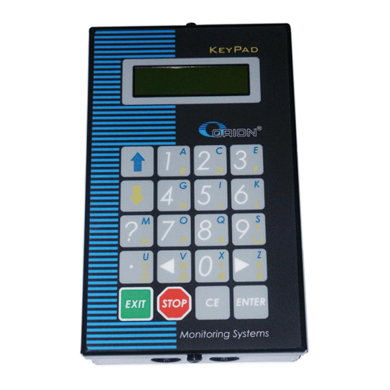
Introduction The KeyPad is the tool that is used to configure an OriLink® monitoring system, as well as initiate dispenses, stop dispenses and check previous dispenses. NOTE! The Orilink® installation manual should be available when installing and configuring a KeyPad. Mechanical installation The KeyPad is mounted at a visible place within comfortable reach of the user using the two holes in the bottom. -
Page 4: Electric Installation
Electric installation The module has a number of connectors, sockets and controls. Where they are depends on if it is a 2 card keypad or a 1 card keypad. 2-boards, buttons pn 203 02 85 and CPU pn 203 02 65 Single board pn 203 02 90 A Single board pn 203 02 90 C, current production 4(13) - Page 5 (A) Shows the replaceable communication driver. (B) If this LED flashes it indicates that the MPDM is working properly. If the LED is unlit or constantly lit something is wrong. (C) The angle of sight (contrast) can be adjusted with this trim screw. (D) Shows the location of the RESET-button.
-
Page 6: Configuration
NOTE! To obtain technical support a copy of the configuration sheet for the complete installation must be sent to: Alentec & Orion AB TECHNICAL SUPPORT Grustagsvägen 4 SE-138 40 ÄLTA SWEDEN orilink@alentec.se... -
Page 7: Recommendation For Setting Addresses
4.5. Recommendation for setting addresses Address Module Each module demands a unique 16 bit hexadecimal address. There 0000 – 0xxx Forbidden are some forbidden and some reserved addresses but it is possible to 1000 – 1xxx MPDM use all addresses between 0001 and 9999. To make it easier to 2000 –... -
Page 8: Using A Keypad Module
Enter menu [KP//Address] by pressing ENTER. Scroll to menu Baud: by pressing or . Press ENTER to get the cursor. Type in the desired Baud rate and acknowledge by pressing ENTER. When the cursor disappears it is finished. Press EXIT twice to leave Set-Up mode. Using a KeyPad module The keyboard of the KeyPad is equipped with multifunctional buttons. -
Page 9: Installing A Serial Port Kit (23 415)
Installing a serial port kit (23 415) (not needed for 23442) The serial port kit can be seen in chapter “9. Technical specification”. Open the keypad and insert the RS-232 serial driver in its socket (H). Make sure that all legs are properly inserted and that the driver chip is oriented the correct way. -
Page 10: Fast Menu Codes
Fast Menu Codes With a PC, the OriLink® WinTools software and a SIO the quick menu that appear when you press “?” can be adjusted. Typing a menu name, the module address and then a code can do this. Password can be used if desired. This code can also be entered together with the address after you have typed SETUP followed by the password. -
Page 11: Optional Back Cover For Panel Model, Pn 233 01 34
10. Optional back cover for panel model, pn 233 01 34 This product is intended as a mechanical protection of the electronics. When this is used the four corner screws fits in the 4 corner threads of the cover. The dimensions are Height = 200 mm Width = 150 mm Depth = 42 mm... -
Page 12: Optional Dc-Dc Converter
11. Optional DC-DC converter (not needed for 23442) By adding a suitable 4-pin SIP package DC-DC converter to the socket (M) the Keypad can give a power supply to connected readers. Suitable DC-DC converters are manufactured by several brands. Here is a list of some of them Brand Example picture Model... -
Page 13: Technical Specification
12. Technical specification Printed circuit board Net ports: 2 pieces of OriLink® ports (E) for data- communication. Connector: 1 piece of serial port connector (G). Socket: 1 piece of 16-pin DIL-socket (H) for a MAX232CPE serial port driver. Socket: 1 piece of 4-pin SIL socket (M) for DC-DC converter.
Need help?
Do you have a question about the OriLink 23441 and is the answer not in the manual?
Questions and answers