
Subscribe to Our Youtube Channel
Related Manuals for Daikin RXYSQ5TAY1B


Summary of Contents for Daikin RXYSQ5TAY1B
- Page 1 Installer and user reference guide VRV IV-S system air conditioner RXYSQ4TAY1B Installer and user reference guide RXYSQ5TAY1B English VRV IV-S system air conditioner RXYSQ6TAY1B...
-
Page 2: Table Of Contents
Table of Contents 6.4.1 About connecting the refrigerant piping ....... 17 Table of Contents 6.4.2 Precautions when connecting the refrigerant piping ..17 6.4.3 Pipe bending guidelines..........17 6.4.4 To braze the pipe end ..........17 6.4.5 Using the stop valve and service port ......17 1 General safety precautions 6.4.6 To remove the pinched pipes........ -
Page 3: General Safety Precautions
1 General safety precautions 11.1 Overview: Troubleshooting............38 20.2.7 Symptom: The user interface display reads "U4" or "U5" and stops, but then restarts after a few minutes.. 54 11.2 Precautions when troubleshooting ..........38 20.2.8 Symptom: Noise of air conditioners (Indoor unit)..54 11.3 Solving problems based on error codes........ -
Page 4: For The User
Make sure installation, testing and applied materials comply with applicable legislation (on top of the For the user instructions described in the Daikin documentation). ▪ If you are not sure how to operate the unit, contact your installer. CAUTION ▪ This appliance can be used by children aged from 8 years and... -
Page 5: Refrigerant
1 General safety precautions ▪ Make sure the area is well ventilated. Do NOT block any NOTICE ventilation openings. ▪ To avoid compressor breakdown, do NOT charge more ▪ Make sure the unit is level. than the specified amount of refrigerant. ▪... -
Page 6: Water
2 About the documentation WARNING NOTICE The use and installation of the application MUST comply Precautions when laying power wiring: with the safety and environmental precautions specified in ▪ Do not connect wiring of different thicknesses to the the applicable legislation. power terminal block (slack in the power wiring may cause abnormal heat). -
Page 7: For The Installer
▪ Format: Digital files on http://www.daikineurope.com/support- and-manuals/product-information/ ▪ The full set of latest technical data is available on the Daikin extranet (authentication required). Latest revisions of the supplied documentation may be available on the regional Daikin website or via your dealer. -
Page 8: About The Units And Options
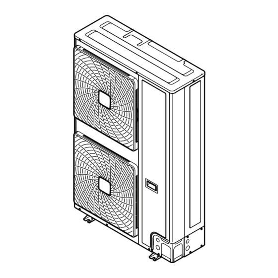
4 About the units and options Code Explanation 1× 1× 1× 1× European market Minor model change indication About the outdoor unit This installation manual concerns the VRV IV-S, full inverter driven, 1× 1× 2× 1× heat pump system. These units are intended for outdoor installation and aimed for air to air heat pump applications. -
Page 9: Possible Combinations Of Indoor Units
5 Preparation 4.5.2 Possible combinations of indoor units 5.2.1 Installation site requirements of the outdoor unit In general following type of indoor units can be connected to a VRV IV-S heat pump system. The list is non-exhaustive and is depending INFORMATION on both outdoor unit model and indoor unit model combinations. -
Page 10: Additional Installation Site Requirements Of The Outdoor Unit In Cold Climates
5 Preparation ▪ Sound sensitive areas (e.g. near a bedroom), so that the operation noise will cause no trouble. Note: If the sound is measured under actual installation conditions, the measured value might be higher than the sound pressure level mentioned in Sound spectrum in the data book due to environmental noise and sound reflections. -
Page 11: Securing Safety Against Refrigerant Leaks
–5°C for 5 days or longer, with relative humidity independent refrigerant systems, use the amount of levels exceeding 95%, we recommend to apply a Daikin refrigerant with which each separate system is charged. range specifically designed for such application and/or to... -
Page 12: Preparing Refrigerant Piping
5 Preparation 3 Calculate the refrigerant density using the results of the 5.3.3 To select the piping size calculations in steps 1 and 2 above. If the result of the above Determine the proper size referring to following tables and reference calculation exceeds the maximum concentration level, a figure (only for indication). -
Page 13: To Select Refrigerant Branch Kits
5 Preparation E: Piping between BP unit and RA DX indoor unit Outdoor unit Piping outer diameter size (mm) capacity type (HP) Gas pipe Liquid pipe Indoor unit capacity Piping outer diameter size (mm) Standard Size-up index Gas pipe Liquid pipe 15.9 19.1 15~42... -
Page 14: Preparing Electrical Wiring
5 Preparation Requirement Limit VRV DX RA DX Maximum length first branch kit-indoor unit 40 m 40 m ▪ Example 1.1, unit 8: b+c+d+e+f+g+p≤Limit ▪ Example 1.2, unit 6: b+h≤Limit ▪ Example 1.2, unit 8: i+k≤Limit ▪ Example 1.3, unit 8: i≤Limit ▪ Example 2, unit 18: b+m≤Limit Maximum length outdoor-BP 55 m ▪... -
Page 15: Safety Device Requirements
6 Installation ▪ EN/IEC 61000‑3‑12 provided that the short-circuit power S INFORMATION greater than or equal to the minimum S value at the interface For installation of the indoor unit (mounting the indoor unit, point between the user's supply and the public system. connecting the refrigerant piping to the indoor unit, ▪... -
Page 16: To Provide The Installation Structure
6 Installation ▪ Install the unit on a base to make sure that there is a proper 6.3.3 To provide the installation structure drainage in order to avoid ice accumulation. Check the strength and level of the installation ground so that the ▪... -
Page 17: Connecting The Refrigerant Piping
6 Installation 6.4.4 To braze the pipe end Connecting the refrigerant piping NOTICE 6.4.1 About connecting the refrigerant piping Precautions when connecting field piping. Add brazing material as shown in the figure. Before connecting the refrigerant piping ≤Ø25.4 Make sure the outdoor and indoor units are mounted. Typical workflow Connecting the refrigerant piping involves: ▪... -
Page 18: To Remove The Pinched Pipes
6 Installation Service port ▪ After handling the service port, make sure to tighten the service Stop valve cover port cover securely. For the tightening torque, refer to the table Hexagon hole below. Shaft Seal ▪ Check for refrigerant leaks after tightening the service port cover. To open the stop valve Tightening torques 1 Remove the stop valve cover. -
Page 19: To Connect The Refrigerant Piping To The Outdoor Unit
6 Installation 4 Do the following: ▪ Connect the liquid pipe (a) to the liquid stop valve. (brazing) ▪ Connect the gas pipe (b) to the gas stop valve. (brazing) NOTICE When brazing: First braze the liquid side piping, then the gas side piping. -
Page 20: To Connect The Refrigerant Branching Kit
6 Installation 6 Seal all gaps (example: a) to prevent snow and small animals Checking the refrigerant piping from entering the system. 6.5.1 About checking the refrigerant piping Refrigerant piping works are Finish piping work. finished? WARNING The indoor units and/or Use procedure: Provide adequate measures to prevent that the unit can be outdoor unit were already... -
Page 21: Checking Refrigerant Piping: General Guidelines
6 Installation For more information on the state of the valves, refer to 3 Should the pressure rise, the system may either contain "6.5.3 Checking refrigerant piping: Setup" on page 21. moisture (see vacuum drying below) or have leaks. To check for leaks: Pressure leak test 6.5.2 Checking refrigerant piping: General guidelines... -
Page 22: Charging Refrigerant
6 Installation ▪ Reinforce the insulation on the refrigerant piping according to the NOTICE installation environment. Be sure to turn on the power 6 hours before operation in order to have power running to the crankcase heater and Ambient Humidity Minimum thickness to protect the compressor. -
Page 23: To Charge Refrigerant
6 Installation Charging refrigerant (in manual additional refrigerant charge Indoor units Total CR CR per type mode) VRV DX RA DX The remaining additional refrigerant charge can be charged by RA DX 100~130% — 100~130% operating the outdoor unit by means of the manual additional 80~130% —... -
Page 24: Error Codes When Charging Refrigerant
6 Installation NOTICE After adding the refrigerant, do not forget to close the lid of the refrigerant charging port. The tightening torque for the lid is 11.5 to 13.9 N•m. 6.7.5 Error codes when charging refrigerant INFORMATION If a malfunction occurs, the error code is displayed on the user interface of the indoor unit. -
Page 25: Precautions When Connecting Electrical Wiring
6 Installation WARNING ▪ After finishing the electrical work, confirm that each electrical component and terminal inside the electrical components box is connected securely. ▪ Make sure all covers are closed before starting up the unit. NOTICE Do not operate the unit until the refrigerant piping is complete. -
Page 26: To Connect The Electrical Wiring On The Outdoor Unit
6 Installation X1M (A1P) ▪ If stranded conductor wires are being used, install a round crimp- style terminal on the tip. Place the round crimp-style terminal on TO MULTI TO IN/D TO OUT/D UNIT the wire up to the covered part and fasten the terminal with the appropriate tool. -
Page 27: Finishing The Outdoor Unit Installation
7 Configuration 6.9.2 To close the outdoor unit Routing through Choose one of the 3 possibilities: the frame NOTICE When closing the outdoor unit cover, make sure that the tightening torque does NOT exceed 4.1 N•m. a Power supply cable b Transmission wiring cable Connecting to the When cables are routed from the unit, a frame... -
Page 28: To Access The Field Setting Components
7 Configuration Mode Description Display Mode 2 Mode 2 is used to change the field settings of 7‑LEDs display the system. Consulting the current field setting (field settings) H1P: Shows the mode value and changing the current field setting H2P~H7P: Shows the settings and values, represented in binary value is possible. -
Page 29: To Use Mode 1
7 Configuration Action Button/display Start from the default situation. BS1 [5 s] Select mode 2. BS2 [X×] Default situation (H1P OFF) Select setting 8. Mode 1 (H1P flashing) ("X×" depends on the setting Mode 2 (H1P ON) Press BS1. that you want to select.) BS1 [5 s] Press BS1 for at least 5 s. -
Page 30: Mode 2: Field Settings
7 Configuration Value / Description Setting Value / Description Shows the status of power consumption limitation operation. [1‑5] It can be convenient to check if the total number of indoor units Shows the total number of Unit is currently not operating under power which are installed match the connected indoor units. - Page 31 7 Configuration Setting Value Setting Value Description Description binary) binary) [2‑20] Deactivated. [2‑25] Level 1 Level 3<Level Level 2 (= binary 1) 2<Level 1 Manual additional refrigerant (default) Low noise operation level via (default) charge. the external control adaptor. Activated. Level 3 In order to add the additional If the system needs to be...
-
Page 32: Energy Saving And Optimum Operation
7 Configuration Setting Value Energy saving and optimum Description operation binary) This heat pump system is equipped with advanced energy saving [2‑31] functionality. Depending on the priority, emphasises can be put on (= binary 1) energy saving or comfort level. Several parameters can be selected, Power consumption limitation resulting in the optimal balance between energy consumption and level (step 2) via the external... -
Page 33: Available Comfort Settings
7 Configuration To activate this in… Change… To activate this in… Change… Heating operation [2‑9] to the appropriate value, Heating operation [2‑43]=2 matching the requirements of the This setting is used in pre-designed system containing conjunction with setting [2‑9]. a high sensible solution. Mild [2‑8] target (°C) -
Page 34: Example: Automatic Mode During Cooling
7 Configuration 7.3.3 Example: Automatic mode during cooling 7.3.4 Example: Automatic mode during heating 100% 100% 49°C 46°C 6°C 3°C 35°C Actual load curve 2°C Virtual load curve (initial capacity automatic mode) Virtual target value (initial evaporation temperature value Virtual load curve (default automatic mode peak capacity) automatic mode) Load curve Required evaporation temperature value... -
Page 35: Commissioning
8 Commissioning Field wiring Commissioning Be sure that the field wiring has been carried out according to the instructions described in the chapter Overview: Commissioning "6.8 Connecting the electrical wiring" on page according to the wiring diagrams and according to the After installation and once the field settings are defined, the installer applicable legislation. -
Page 36: Checklist During Commissioning
9 Hand-over to the user 4 Check the test operation results on the outdoor unit 7‑LEDs Checklist during commissioning display. To perform a test run. Completion Description Normal completion 8.4.1 About test run Abnormal The procedure below describes the test operation of the complete completion Refer to "8.4.3 Correcting after abnormal... -
Page 37: Overview: Maintenance And Service
10 Maintenance and service 5 After the service is finished, plug the junction connector back in. NOTICE Otherwise the malfunction code will be displayed and In Europe, the greenhouse gas emissions of the total normal operation will not be performed. refrigerant charge in the system (expressed as tonnes For details refer to the wiring diagram labelled on the back of the -equivalent) is used to determine the maintenance... -
Page 38: 11 Troubleshooting
11 Troubleshooting DANGER: RISK OF ELECTROCUTION Troubleshooting WARNING 11.1 Overview: Troubleshooting Prevent hazard due to the inadvertent resetting of the thermal cut-out: this appliance must NOT be supplied Before troubleshooting through an external switching device, such as a timer, or Carry out a thorough visual inspection of the unit and look for connected to a circuit that is regularly turned ON and OFF obvious defects such as loose connections or defective wiring. - Page 39 12 Disposal Main code Cause Solution High pressure sensor malfunction (S1NPH): open circuit / Check connection on PCB or actuator. short circuit - A1P (X32A) Low pressure sensor malfunction (S1NPL): open circuit / Check connection on PCB or actuator. short circuit - A1P (X31A) Transmission outdoor unit - inverter: INV1 / FAN1 / FAN2 Check connection.
- Page 40 13 Technical data Technical data A subset of the latest technical data is available on the regional Daikin website (publicly accessible). The full set of latest technical data is available on the Daikin extranet (authentication required). 13.1 Overview: Technical data This chapter contains information about: •...
- Page 41 13 Technical data 13.3 Service space: Outdoor unit Outdoor unit: • When mounting units side by side, the piping route must be to the front, to the back or downwards. In this case the piping route to the side is not possible.
- Page 42 13 Technical data Multiple rows of units ( b (mm) ≥100 ≥100 ≤½H b≥250 ½H <H ≤H b≥300 ≥100 ≥100 ≥100 >H ≥2000 ≥3000 ≥100 ≥200 ≥100 ≥1000 ≥600 ≥1500 Stacked units (max. 2 levels) ( ≥100 ≥100 ≥300 ≥1000 ≥100 ≥100 ≥100...
- Page 43 13 Technical data 13.4 Components: Outdoor unit X1M (A1P) S1PH Heat exchanger Solenoid valve (oil) Service port (high pressure) Solenoid valve (4‑way valve) Oil separator Switch box Service port (refrigerant charge) Stop valve (gas) Stop valve (liquid) Cable tie mountings (to fix the field wiring with cable ties to ensure stress relief) Subcool heat exchanger Accumulator...
- Page 44 13 Technical data 13.5 Piping diagram: Outdoor unit S1NPH S1PH S1NPL INV M1C Stop valve (gas) Stop valve (liquid) Filter (4×) Accumulator Subcool tube heat exchanger Pressure regulating valve Heat exchanger Service port (high pressure) Oil separator Capillary tube (2×) Service port (refrigerant charge) Compressor M1F-M2F...
- Page 45 13 Technical data 13.6 Wiring diagram: Outdoor unit The wiring diagram is delivered with the unit, located at the inside of the service cover. 3N~ 380-415 V 50 Hz L1 L2 L3 N H5P H6P Q1RP P> X11A S1PH E L2A 1234 L2 L3 F410U...
- Page 46 13 Technical data Magnetic contactor (M1C) (A3P) Magnetic relay (A2P) Magnetic relay (Y1S) Magnetic relay (Y3S) Magnetic relay (E1HC) Reactor Motor (compressor) M1F, M2F Motor (upper and lower fan) Switching power supply (A1P) (A3P) Q1RP Reverse phase protector R2, R3 Resistor Resistor (current sensor) (A4P) (A5P) Resistor (current limiting)
- Page 47 14 About the system For the user About the system User interface The indoor unit part of VRV IV-S heat pump system can be used for CAUTION heating/cooling applications. The type of indoor unit which can be Never touch the internal parts of the controller. used depends on the outdoor units series.
- Page 48 17 Operation Hot start Cooling Heating In order to prevent cold air from blowing out of an indoor unit at the Outdoor –5~46°C DB –20~21°C DB start of heating operation, the indoor fan is automatically stopped. temperature –20~15.5°C WB The display of the user interface shows .
- Page 49 17 Operation BP box (required to connect Residential Air (RA) or Sky Air 17.4 Adjusting the air flow direction (SA) direct expansion (DX) indoor units) Residential Air (RA) direct expansion (DX) indoor units Refer to the operation manual of the user interface. User interface (wireless, dedicated depending on indoor unit type) 17.4.1...
- Page 50 18 Energy saving and optimum operation idea, the system automatically starts increasing its refrigerant Energy saving and optimum temperature, automatically reducing the delivered capacity and operation increasing the system's efficiency. Hi-sensible/economic (cooling/heating) Observe the following precautions to ensure the system operates properly.
- Page 51 19 Maintenance and service 19.1 Maintenance after a long stop 19.4 After-sales service and warranty period 19.4.1 Warranty period E.g., at the beginning of the season. ▪ This product includes a warranty card that was filled in by the ▪ Check and remove everything that might be blocking inlet and dealer at the time of installation.
- Page 52 20 Troubleshooting ▪ Operation of the unit is assumed to be 10 hours/day and WARNING 2,500 hours/year. Stop operation and shut off the power if anything unusual occurs (burning smells etc.). NOTICE Leaving the unit running under such circumstances may ▪ The table indicates main components. Refer to your cause breakage, electric shock or fire.
- Page 53 20 Troubleshooting If after checking all above items, it is impossible to fix the problem Main code Contents yourself, contact your installer and state the symptoms, the complete High pressure sensor malfunction (S1NPH) model name of the unit (with manufacturing number if possible) and Low pressure sensor malfunction (S1NPL) the installation date (possibly listed on the warranty card).
- Page 54 21 Relocation 20.2.3 Symptom: The fan strength does not 20.2.9 Symptom: Noise of air conditioners correspond to the setting (Indoor unit, outdoor unit) The fan speed does not change even if the fan speed adjustment ▪ A continuous low hissing sound is heard when the system is in button is pressed.
- Page 55 Optional equipment Equipment made or approved by Daikin that can be combined with the product according to the instructions in the accompanying documentation. Field supply Equipment not made by Daikin that can be combined with product according instructions accompanying documentation.
- Page 56 4P482257-1 2017.03...
Need help?
Do you have a question about the RXYSQ5TAY1B and is the answer not in the manual?
Questions and answers