Advertisement
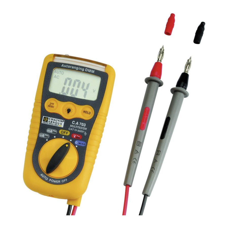
DESCRIPTION
FRONT PANEL

- Contact-free voltage detection sensor
- Voltage indication light bar
- LCD
- Measurement selection key
- Switch
- Flashlight
- Flashlight On key
- HOLD key
- Battery compartment
- Probe tips on the tester itself
LCD

- Diode
- Continuity
- Display unit HOLD
- Battery low indicator
- Value measured
- Voltage
- Current
- Resistance
- Automatic ranges
- AC
- DC
- Negative polarity
INTRODUCTION
You have just acquired a Digital Pocket Multimeter. Congratulations for your choice and thank you for your trust in the quality of our products.
This instrument belongs to the CHAUVIN ARNOUX range of products. This is a simple use multimeter capable of measuring the following measurements: voltages, resistance, continuity and diode.
PRECAUTIONS FOR USE
Before use, carefully read the following safety precautions.


Instructions followed by the sign  must be obeyed to avoid accidental burn or electric shock.
STANDARD:
This device is not a voltage verification device according to IEC 61243-3 standard. Overvoltage Category IV, Max. Input Voltage: 600 V
MEASUREMENT CATEGORIES (IEC 61010-2-033)
Measurement category II:
Measurement category II is applicable to test and measuring circuits connected directly to utilization points (socket outlets and similar points) of the low-voltage MAINS installation. This part of the installation is expected to have a minimum of two levels of overcurrent protective devices between the transformer and the connecting points of the measuring circuit.
Example: measurements on MAINS CIRCUITS of household appliances, portable tools and similar equipment.
Measurement category III : Measurement category III is applicable to test and measuring circuits connected to the distribution part of the building's low-voltage MAINS installation. This part of the installation is expected to have a minimum of one level of over-current protective devices between the transformer and possible connecting points.
Example : measurements on distribution boards (including secondary electricity meters), circuitbreakers, wiring, including cables, busbars, junction boxes, switches, socket -outlets in the fixed installation, and equipment for industrial use and some other equipment such as stationary motors with permanent connection to the fixed installation.
Measurement category IV : Measurement category IV is applicable to test and measuring circuits connected at the source of the building's low-voltage MAINS installation. This part of the installation could have no overcurrent protective devices between the transformer and connecting points of the measuring circuit.
Example: measurements on devices installed before the main fuse or circuit breaker in the building installation.

TO WORK SAFETY:
- Pay special attention when measuring the voltage of 30 VAC RMS and 50 VDC.
- Never apply input signals exceeding the maximum rating input value.
- Always keep your fingers behind the finger guards on the probe when making measurement.
- Be sure to disconnect the test pins from the circuit when changing the function.
- Never use meter if the meter or test leads are damaged or broken.
- Before performing continuity or resistance measurement, make sure that no voltage is present.
- Before starting measurement, make sure that the function is properly set in accordance with the measurement.
- Never use without gloves for electricians and other equipment recommended by the Law.
- Never use in a dusty or wet environment. - Never replace the batteries without disconnecting the leads.
- Never open the meter except when replacing batteries. The one part of the casing which can be opened is the battery compartment.
MAINTENANCE
UNPACKING, RE-PACKING
All equipment has been mechanically and electrically checked before being dispatched. However, it is wise to check briefly that equipment was not damaged during transport. If so, please contact our.
Marketing Department as soon as possible and claim carrier legal reserve.
If the equipment is being sent back, please preferably use original packaging and indicate as clearly as possible the reasons for sending it back on a note enclosed with the equipment.
METROLOGICAL VERIFICATION
Return your instrument to your distributor for any work to be done within or outside the guarantee.
MAINTENANCE
Use a damp cloth to clean the exeterior housing, ensure no water or soap is allowed inside the tester.
STORAGE
If the tester must not be used for periods longer than 60 days, remove the batteries and store them separately.
FUNCTIONAL DESCRIPTION
CONTACT-FREE AC PHASIS DETECTION
Attention: Test the instrument on line power before use to check that it is in good working order.
This function works whether the instrument is Off or On, and whatever the setting of the switch.
- Place the contact-free AC phasis sensor (item 1) near the socket, cable, or connector to be tested.
- The voltage indication light bar (item 2) lights if an AC voltage between 100 and 600V with respect to earth is present.
- This function can thus be used to tell the phase and neutral apart.
Attention: the presence of electrostatic fields (friction, etc.) may induce untimely lighting of the light bar.
Likewise, the sensitivity of the instrument in the presence of strong electromagnetic fields (e.g. in electrical cabinets) may lead to errored voltage present indications. We accordingly recommend using an instrument complying with standard IEC 61243-3 (e.g. the C.A 760) for your voltage detection operations.
AC OR DC VOLTAGE MEASUREMENT
- Set the switch to the «V» function.
The default measurement mode is AC.
Press the "2nd AC/DC" key to switch from AC to DC or vice versa.
- Place the black probe tip on one pole, then the red probe tip on the other pole.
- Read the value on the display unit.
- Finally, withdraw the red probe tip, then the black probe tip.
AC OR DC CURRENT MEASUREMENT
- Set the switch to the «mA» function, then to «µA» if you want to measure µA.
The default measurement mode is AC. Press the "2nd AC/DC" key to switch from AC to DC and vice versa.
- Place the black probe tip on one pole, then the red probe tip on the other pole.
- Read the value on the display unit.
- Finally, withdraw the red probe tip, then the black probe tip.
Note: the instrument is protected by a 600V/200mA electronic fuse than can be reset automatically
RESISTANCE MEASUREMENT
- Work with power off.
- Set the switch to « Ω ».
- Place the red and black probe tips on the object to be measured.
- Read the value on the display unit.
Note: the instrument is protected up to 600V rms on this input.
CONTINUITY CHECK
- Work in a power-off condition.
- Set the switch to Ω
![]() .
. - Press « 2nd AC/DC » repeatedly until «
![]() » appears.
» appears. - Place the red and black probe tips on the circuit or conductor to be measured.
The beeper sounds if the circuit is closed and connected. - Withdraw the probe tips from the tested object.
 .
. » appears.
DIODE TEST
- Work in a power-off condition.
- Set the switch to Ω
![]() .
. - Press « 2nd AC/DC » repeatedly until «
![]() » appears.
» appears. - Connect the cords to the diode to be tested.
 » appears.
HOLD FUNCTION
- Connect the probe tips.
- Press the HOLD key to freeze the screen.
- The text « HOLD » appears on the screen and the buzzer sounds.
- Withdraw the probe tips.
- Read the value on the display unit.
FLASHLIGHT FUNCTION
This function works whether the instrument is Off or On, whatever the setting of the switch. - Press the key (no.7) and hold it down as long as you want the flashlight (item 6) to remain lit.
AUTO POWER OFF
- The C.A 703 switches itself off automatically 15' after the last operation.
- Any action on the HOLD key or the switch resets the timer.
REPLACING THE BATTERIES
If the « battery » symbol appears, the batteries are too weak. Replace them with two 1.5V AAA batteries:
- Disconnect the probe tips.
- Set the switch to OFF.
- Remove the screw from the battery compartment cover, then replace the batteries, and close back and screw the cover back down (item 9).
GENERAL CHARACTERISTICS
SPECIFICATIONS
- Measurement method: mean
- Passband: 40-400Hz
- Input impedance (VAC & DC): 7.5MΩ
- Display unit: 1,999 points
- Range selection: automatic
- Range overshoot: display «OL» in resistance mode.
- Polarity indication: «-» sign
- Battery condition indication: «battery low» symbol
- Sampling frequency: approx. twice per s. - Operating environment: 0 to 40°C; RH<80% no condensation.
- Storage condition: -10°C to 50°C; RH<70%, no condensation.
- Power source: 2 AAA 1.5V batteries.
- Mass: approx. 145g.
- Dimensions: 104(l) x 55(w) x 32.5(h)mm
TECHNICAL SPECIFICATION
Metrology
Reference conditions: 18°C – 28°C; RH < 80%, no condensation.
Standard:
IEC 61010-1
IEC 61010-031
IEC 61010-2-033
| Function | Range | Accuracy | Protection |
| V (DC) | 200mV, | ±(0.5%L + 3d) | |
| 2.000V, 20.00V, 200.0V, 600V | ±(1.2%L + 3d) | ||
| > 600V | Outside specifications | ||
| V (AC) 40-400Hz | 2.000V, 20.00V | ±(1.0%L + 8d) | |
| 200.0V, 600V | ±(2.3%L + 10d) | ||
| > 600V | Outside specifications | ||
| I (DC) | 200.0µA, 2000µA | ±(2.0%L+ 8d) | 200 mA/ 500V electronic fuse |
| 20.00mA, 200.0mA | ±(2.0%L+ 8d) | ||
| I (AC) | 200.0µA, 2000µA | ±(2.5%L + 10d) | 200 mA/ 500V electronic fuse |
| 20.00mA, 200.0mA | ±(2.5%L + 10d) | ||
| Resistance | 200.0Ω | ±(0.8%L + 5d) | 600V rms |
| 2.000kΩ, 20.00kΩ, 200.0kΩ | ±(1.2%L + 5d) | 600V rms | |
| 2.000MΩ | ±(5.0%L + 5d) | 600V rms | |
| 20.00MΩ | ±(10.0%L + 5d) | 600V rms | |
| Diode test | 1.999V | 600V rms | |
| Continuity test | 600V rms | ||
| Buzzer | 199.9Ω | R<Ω | 600V rms |
TO ORDER
C.A 703 Multitester
P01191740Z
Delivered with two permanently connected leads with test probes, 2 AAA (1.5V) batteries, and these operating instructions.
Deutschland
Ohmstraße 1 - 77694 KEHL /RHEIN
Tél: (07851) 99 26-0 - Fax: (07851) 99 26-60
España
C/ Roger de Flor N°293 - Planta 1
08025 BARCELONA
Tél: 902 20 22 26 - Fax: 934 59 14 43
Italia
Via Sant' Ambrogio, 23/25
20846 MACHERIO (MB)
Tél: (039) 245 75 45 - Fax: (039) 481 561
Österreich
Slamastrasse 29/2/4 - 1230 WIEN
Tél: 01 61 61 9 61-0 - Fax: 01 61 61 9 61 61
Schweiz
Moosacherstrasse 15 - 8804 AU / ZH
Tél: 044 727 75 55 - Fax: 044 727 75 56
UK
Unit 1 - Nelson Ct - Flagship Sq - Shaw Cross
Business Pk - Dewsbury, West Yorkshire - WF12 7TH
Tél: 01924 460 494 - Fax: 01924 455 328
Middle East
P.O BOX 60-154 - 1241 2020 Jal el dib- BEIRUT
Tél: (01) 890 425 - Fax: (01) 890 424
China - Shanghai Pujiang Enerdis Inst. CO. LTD
3 Floor, Buildind 1 n°381 Xiang De Road Hongkou District - 200081 - SHANGHAI
Tél: +86 21 65 21 51 96 - Fax: +86 21 65 21 61 07
USA - d.b.a AEMC Instruments
200 Foxborough Blvd - Foxborough - MA 02035
Tél: (508) 698-2115 - Fax: (508) 698-2118
190, rue Championnet - 75876 PARIS Cedex 18 - FRANCE
Tél. (33) 01 44 85 44 85 - Fax (33) 01 46 27 73 89
http://www.chauvin-arnoux.com

Documents / Resources
References
Download manual
Here you can download full pdf version of manual, it may contain additional safety instructions, warranty information, FCC rules, etc.
Download Chauvin Arnoux C.A 703 - Digital Pocket Multimeter Manual
Advertisement
Thank you! Your question has been received!


Need Assistance?
Do you have a question about the C.A 703 that isn't answered in the manual? Leave your question here.