
Subscribe to Our Youtube Channel
Related Manuals for Miller PipeWorx 350


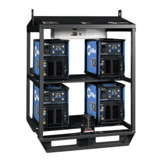
Summary of Contents for Miller PipeWorx 350
- Page 1 OM-259463B 2018−10 Processes Multiprocess Welding Description PipeWorx 350 FieldPro Racks File: Multiprocess For product information, Owner’s Manual translations, and more, visit www.MillerWelds.com...
- Page 2 We know you don’t have time to do it any other way. That’s why when Niels Miller first started building arc welders in 1929, he made sure his products offered long-lasting value and superior quality.
-
Page 3: Table Of Contents
TABLE OF CONTENTS SECTION 1 − SAFETY PRECAUTIONS - READ BEFORE USING ....... . . 1-1. -
Page 5: Section 1 − Safety Precautions - Read Before Using
SECTION 1 − SAFETY PRECAUTIONS - READ BEFORE USING som 2018−01 Protect yourself and others from injury — read, follow, and save these important safety precautions and operating instructions. 1-1. Symbol Usage DANGER! − Indicates a hazardous situation which, if Indicates special instructions. - Page 6 D Do not cut or weld on tire rims or wheels. Tires can explode if heat- FUMES AND GASES can be hazardous. ed. Repaired rims and wheels can fail. See OSHA 29 CFR 1910.177 listed in Safety Standards. D Do not weld on containers that have held combustibles, or on Welding produces fumes and gases.
-
Page 7: Additional Symbols For Installation, Operation, And Maintenance
D Never weld on a pressurized cylinder − explosion will result. CYLINDERS can explode if damaged. D Use only correct compressed gas cylinders, regulators, hoses, and fittings designed for the specific application; maintain them Compressed gas cylinders contain gas under high and associated parts in good condition. -
Page 8: California Proposition 65 Warnings
H.F. RADIATION can cause interference. ARC WELDING can cause interference. D High-frequency (H.F.) can interfere with radio D Electromagnetic energy can interfere with navigation, safety services, computers, and sensitive electronic equipment such as communications equipment. computers and computer-driven equipment such as robots. D Have only qualified persons familiar with electronic equipment D Be sure all equipment in the welding area is electromagnetically perform this installation. -
Page 9: Section 2 − Consignes De Sécurité − Lire Avant Utilisation
SECTION 2 − CONSIGNES DE SÉCURITÉ − LIRE AVANT UTILISATION som_2018−01_fre Pour écarter les risques de blessure pour vous−même et pour autrui — lire, appliquer et ranger en lieu sûr ces consignes relatives aux précautions de sécurité et au mode opératoire. 2-1. - Page 10 D Déplacer toutes les substances inflammables à une distance de LES PIÈCES CHAUDES peuvent 10,7 m de l’arc de soudage. En cas d’impossibilité les recouvrir provoquer des brûlures. soigneusement avec des protections homologués. D Ne pas toucher à mains nues les parties chaudes. D Ne pas souder dans un endroit là...
-
Page 11: Dangers Supplémentaires En Relation Avec L'installation, Le Fonctionnement Et La Maintenance
D Protéger les bouteilles de gaz comprimé d’une chaleur excessive, Les CHAMPS ÉLECTROMAGNÉTIQUES (CEM) des chocs mécaniques, des dommages physiques, du laitier, des peuvent affecter les implants médicaux. flammes ouvertes, des étincelles et des arcs. D Placer les bouteilles debout en les fixant dans un support station- D Les porteurs de stimulateurs cardiaques et naire ou dans un porte-bouteilles pour les empêcher de tomber ou autres implants médicaux doivent rester à... -
Page 12: Proposition Californienne 65 Avertissements
D Effectuer régulièrement le contrôle et l’entretien de l’installation. LIRE LES INSTRUCTIONS. D Maintenir soigneusement fermés les portes et les panneaux des sources de haute fréquence, maintenir les éclateurs à une distan- D Lire et appliquer les instructions sur les ce correcte et utiliser une terre et un blindage pour réduire les étiquettes et le Mode d’emploi avant l’instal- interférences éventuelles. -
Page 13: Section 3 − Definitions
SECTION 3 − DEFINITIONS 3-1. Manufacturer’s Warning Label Definitions Warning! Watch Out! There are possible hazards as shown by the symbols. Safe1 2012−05 Beware of electric shock from wiring. Safe94 2012−08 Do not stack racks. Lift only with proper equipment and correct procedures. Safe99 2012−08 3-2. -
Page 14: Section 4 − Specifications
SECTION 4 − SPECIFICATIONS 4-1. Serial Number And Rating Label Location The serial number and rating information for this product is located on the back panel of the control box. Use rating label to determine input power requirements and/or rated output. For future reference, write serial number in space provided on back cover of this manual. 4-2. -
Page 15: Section 5 − Installation
SECTION 5 − INSTALLATION 5-1. Selecting A Location Do not move or operate unit where it could tip. Movement Special installation may be Location And Airflow required where gasoline or volatile liquids are present − see NEC Article 511 or CEC Section 20. -
Page 16: Installing Welding Power Source Onto Rack
5-3. Installing Welding Power Source Onto Rack Have only qualified persons make this installation. Turn welding power sources before inspecting or installing rack. Rear Rack Mounting Bracket Loosely attach one rack mounting bracket (with the weld nuts facing up) on the back of the rack with 2 screws. -
Page 17: Welding Power Source Input Power Connections
5-4. Welding Power Source Input Power Connections Side View Tools Needed: Ref. 221 549 / 220 156 / 804 787-B / 801 702-C rack is numbered. The numbers on the control Input Conductors Disconnect input power to rack before box access door refer to the similarly located working on wiring for any welding Power Fuse Block Terminals strain relief connectors and fuse block inside... -
Page 18: Common Work Connections
5-5. Common Work Connections Tools Needed: 3/4 in. 254 710-A Determine cable sizes according to welding Turn Off welding power sources by INADEQUATE WORK CABLE CON- power source Owner’s Manual. Cable must placing Power circuit breakers in the NECTIONS can cause serious dam- reach from negative (−) output receptacle to Off position before making any weld age to input power service and create... -
Page 19: Connecting Input Power To Rack
5-6. Connecting Input Power To Rack GND/PE Earth Ground Ref. 801 702-C / 804 787-B / 803 766-C / input3 2013−04 OM-259463 Page 15... - Page 20 5-6. Connecting 3-Phase Input Power (Continued) Control Box Input Power Connections Close and secure access door on control Installation must meet all National box. and Local Codes − have only qualified Control Box persons make this installation. Disconnect Device Input Power Connec- Disconnect and lockout/tagout input tions Open access door.
-
Page 21: Electrical Service Guide For 4-Pack Racks
5-7. Electrical Service Guide For 4-Pack Racks Ref. Elec Serv 2014−01 Failure to follow these electrical service guide recommendations could create an electric shock or fire hazard. These recommenda- tions are for a dedicated circuit sized for the rated output and duty cycle of the welding power source. In dedicated circuit installations, the National Electrical Code (NEC) allows the receptacle or conductor rating to be less than the rating of the circuit protection device. -
Page 22: Weld Output Terminals And Selecting Cable Sizes
5-10. Weld Output Terminals And Selecting Cable Sizes NOTICE − The Total Cable Length in Weld Circuit (see table below) is the combined length of both weld cables. For example, if the power source is 100 ft (30 m) from the workpiece, the total cable length in the weld circuit is 200 ft (2 cables x 100 ft). Use the 200 ft (60 m) column to determine cable size. -
Page 23: Section 6 − Maintenance & Troubleshooting
SECTION 6 − MAINTENANCE & TROUBLESHOOTING 6-1. Routine Maintenance Maintain more often Disconnect power before maintaining. during severe conditions. n = Check Z = Change ~ = Clean l = Replace Reference * To be done by Factory Authorized Service Agent l Damaged Or Unreadable ~ Connections At Isolated Tighten Connections To... -
Page 24: Line Fuse Size Requirements
6-3. Line Fuse Size Requirements This chart is a general guideline and may not meet specifications for all applications. Fuses must be selected by a qualified person. 220 551-B 6-4. Troubleshooting Trouble Remedy No weld output from any welding Place line disconnect switch in On position (see Section 5-6). power sources;... -
Page 25: Section 7 − Electrical Diagrams
SECTION 7 − ELECTRICAL DIAGRAMS 220 773-B Figure 7-1. Circuit Diagram For Control Panel In 4-Pack Racks 220 776-C Figure 7-2. Circuit Diagram For Control Panel In 6-Pack Racks OM-259463 Page 21... -
Page 26: Section 8 − Parts List
SECTION 8 − PARTS LIST Hardware is common and not available unless listed. Fig 8-2 Fig 8-3 254714-B Figure 8-1. Main Assembly OM−259463 Page 22... - Page 27 Item Part Description Quantity 6-Pack 4-Pack Figure 8-1. Main Assembly ....183386 Frame, Rack ..........
- Page 28 Hardware is common and not available unless listed. 804765-C Figure 8-2. Control Box Notes OM−259463 Page 24...
- Page 29 Item Part Description Quantity 4-Pack Figure 8-2. Control Box (Fig 8-1 Item 3) 6-Pack ... . +221550 Distribution Box, W/ Holes ........
- Page 30 Hardware is common and not available unless listed. Ref. 804 763-B Figure 8-3. Bracket Assembly Item Part Description Quantity Figure 8-3. Bracket Assembly (Fig 8-1 Item 4) ....602216 Washer, Lock .502idx0.879odx.151T Stl Pld Split.500 .
- Page 31 Effective January 1, 2018 (Equipment with a serial number preface of MJ or newer) This limited warranty supersedes all previous Miller warranties and is exclusive with no other guarantees or warranties expressed or implied. Warranty Questions? LIMITED WARRANTY − Subject to the terms and conditions below, 6 Months —...
- Page 32 Contact the Delivering Carrier to: File a claim for loss or damage during shipment. For assistance in filing or settling claims, contact your distributor and/or equipment manufacturer’s Transportation Department. © ORIGINAL INSTRUCTIONS − PRINTED IN USA 2018 Miller Electric Mfg. LLC 2018−01...
Need help?
Do you have a question about the PipeWorx 350 and is the answer not in the manual?
Questions and answers