Table of Contents
Advertisement
Quick Links
Advertisement
Table of Contents
Troubleshooting

Related Manuals for Miller Dynasty 200 SD


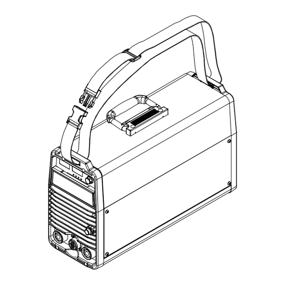
Summary of Contents for Miller Dynasty 200 SD
- Page 1 OM-2240 207688AH 2012−02 Processes TIG (GTAW) Welding Stick (SMAW) Welding Description 115/230/400/460 Volt Models W/AutolineR Arc Welding Power Source Dynasty 200 SD And DX (Including Optional Cart And Cooler) CE And Non-CE Models Visit our website at www.MillerWelds.com...
- Page 2 We know you don’t have time to do it any other way. That’s why when Niels Miller first started building arc welders in 1929, he made sure his products offered long-lasting value and superior quality.
-
Page 3: Table Of Contents
TABLE OF CONTENTS SECTION 1 − SAFETY PRECAUTIONS - READ BEFORE USING ....... . . 1-1. - Page 4 TABLE OF CONTENTS 5-14. Factory Parameter Defaults And Range And Resolution ........5-15.
- Page 5 DECLARATION OF CONFORMITY for European Community (CE marked) products. MILLER Electric Mfg. Co., 1635 Spencer Street, Appleton, WI 54914 U.S.A. declares that the product(s) identified in this declaration conform to the essential requirements and provisions of the stated Council Directive(s) and Standard(s).
-
Page 7: Section 1 − Safety Precautions - Read Before Using
SECTION 1 − SAFETY PRECAUTIONS - READ BEFORE USING som 2011−10 Protect yourself and others from injury — read, follow, and save these important safety precautions and operating instructions. 1-1. Symbol Usage DANGER! − Indicates a hazardous situation which, if Indicates special instructions. - Page 8 D Remove stick electrode from holder or cut off welding wire at FUMES AND GASES can be hazardous. contact tip when not in use. D Wear oil-free protective garments such as leather gloves, heavy Welding produces fumes and gases. Breathing shirt, cuffless trousers, high shoes, and a cap.
-
Page 9: Additional Symbols For Installation, Operation, And Maintenance
1-3. Additional Symbols For Installation, Operation, And Maintenance FIRE OR EXPLOSION hazard. BATTERY EXPLOSION can injure. D Do not install or place unit on, over, or near D Do not use welder to charge batteries or jump combustible surfaces. start vehicles unless it has a battery charging D Do not install unit near flammables. -
Page 10: California Proposition 65 Warnings
1-4. California Proposition 65 Warnings Welding or cutting equipment produces fumes or gases This product contains chemicals, including lead, known to which contain chemicals known to the State of California to the state of California to cause cancer, birth defects, or other cause birth defects and, in some cases, cancer. -
Page 11: Section 2 − Consignes De Sécurité − Lire Avant Utilisation
SECTION 2 − CONSIGNES DE SÉCURITÉ − LIRE AVANT UTILISATION fre_som_2011−10 Pour écarter les risques de blessure pour vous−même et pour autrui — lire, appliquer et ranger en lieu sûr ces consignes relatives aux précautions de sécurité et au mode opératoire. 2-1. - Page 12 Il reste une TENSION DC NON NÉGLIGEABLE dans LE SOUDAGE peut provoquer un les sources de soudage onduleur UNE FOIS incendie ou une explosion. l’alimentation coupée. Le soudage effectué sur des conteneurs fermés tels D Arrêter les convertisseurs, débrancher le courant électrique et que des réservoirs, tambours ou des conduites peut décharger les condensateurs d’alimentation selon les instructions provoquer leur éclatement.
-
Page 13: Dangers Supplémentaires En Relation Avec L'installation, Le Fonctionnement Et La Maintenance
ACCUMULATIONS LES BOUTEILLES peuvent exploser risquent de provoquer des blessures si elles sont endommagées. ou même la mort. Les bouteilles de gaz comprimé contiennent du gaz D Fermer l’alimentation du gaz comprimé en cas sous haute pression. Si une bouteille est endommagée, elle peut exploser. -
Page 14: Proposition Californienne 65 Avertissements
Les PIÈCES MOBILES peuvent RAYONNEMENT HAUTE causer des blessures. FRÉQUENCE (H.F.) risque provoquer des interférences. D Ne pas s’approcher des organes mobiles. D Ne pas s’approcher des points de coincement D Le rayonnement haute fréquence (H.F.) peut tels que des rouleaux de commande. provoquer des interférences avec les équi- pements de radio−navigation et de com- LES FILS DE SOUDAGE peuvent... -
Page 15: Principales Normes De Sécurité
2-5. Principales normes de sécurité Safety in Welding, Cutting, and Allied Processes, ANSI Standard Z49.1, Spectrum Way, Suite 100, Ontario, Canada L4W 5NS (phone: is available as a free download from the American Welding Society at 800-463-6727, website: www.csa-international.org). http://www.aws.org or purchased from Global Engineering Documents Safe Practice For Occupational And Educational Eye And Face Protec- (phone: 1-877-413-5184, website: www.global.ihs.com). - Page 16 OM-2240 Page 10...
-
Page 17: Section 3 − Definitions (Ce Models)
A complete Parts List is available at www.MillerWelds.com SECTION 3 − DEFINITIONS (CE Models) 3-1. Warning Label Definitions Warning! Watch Out! There are possible Breathing welding fumes can be 3.3 Do not weld on drums or any closed hazards as shown by the symbols. hazardous to your health. -
Page 18: Weee Label (For Products Sold Within The Eu)
A complete Parts List is available at www.MillerWelds.com Warning! Watch Out! There are possible hazards as shown by the symbols. Electric shock from wiring can kill. Disconnect input plug or power before working on machine. Hazardous voltage remains on input capacitors after power is turned off. -
Page 19: Symbols And Definitions
A complete Parts List is available at www.MillerWelds.com 3-3. Symbols And Definitions Gas Tungsten Arc Shielded Metal Arc Amperes Panel−Local Welding (GTAW) Welding (SMAW) 3 Phase Static Frequency Volts Voltage Input Converter-Transformer-Rectifier Lift-Arc Start Voltage Output Circuit Breaker Remote (GTAW) Protective Earth Postflow Timer Preflow Timer... -
Page 20: Section 4 − Installation
A complete Parts List is available at www.MillerWelds.com SECTION 4 − INSTALLATION 4-1. Important Information Regarding CE Products (Sold Within The EU) A. Information On Electromagnetic Fields (EMF) This equipment shall not be used by the general public as the EMF limits for the general public might be exceeded during welding. This equipment is built in accordance with EN 60974−1 and is intended to be used only in an occupational environment (where the general public access is prohibited or regulated in such a way as to be similar to occupational use) by an expert or an instructed person. -
Page 21: Specifications
A complete Parts List is available at www.MillerWelds.com 4-3. Specifications Amperes Input At Rated Output, Max. Welding Rated Peak Rated 50/60Hz Open-Cir- Input Power Amperage Striking Output Rating cuit Voltage Range ** Voltage (Up) (Uo) 130 A @ 25.2 ∇ Three-Phase 12.3 VDC,... -
Page 22: Dc Volt-Ampere Curves
A complete Parts List is available at www.MillerWelds.com 4-4. DC Volt-Ampere Curves Volt-ampere curves show minimum and maximum voltage and amper- age output capabilities of welding 115VAC Input; DC Output power source. Curves of other set- tings fall between curves shown. Stick Max. -
Page 23: Ac Volt-Ampere Curves
A complete Parts List is available at www.MillerWelds.com 4-5. AC Volt-Ampere Curves Volt-ampere curves show minimum 115VAC Input; AC Output and maximum voltage and amper- age output capabilities of welding power source. Curves of other set- tings fall between curves shown. Stick Max. -
Page 24: Duty Cycle And Overheating
A complete Parts List is available at www.MillerWelds.com 4-6. Duty Cycle And Overheating Duty Cycle is percentage of 10 min- utes that unit can weld at rated load without overheating. If unit overheats, output stops, a Help message is displayed (see Section 7-3), and cooling fan runs. -
Page 25: Selecting A Location
A complete Parts List is available at www.MillerWelds.com 4-7. Selecting A Location Line Disconnect Device Locate unit near correct input power supply. Dimensions And Weight Special installation may be required where gasoline or 48.5 lb (22.0 kg) volatile liquids are present − see NEC Article 511 or CEC Section 20. -
Page 26: Weld Output Terminals And Selecting Cable Sizes
****For distances longer than 100 ft (30 m) and up to 200 ft (60 m), use direct current (DC) output only. For distances longer than those shown in this guide, call a factory applications rep. at 920-735-4505 (Miller) or 1-800-332-3281 (Hobart). -
Page 27: Remote 14 Receptacle Information
A complete Parts List is available at www.MillerWelds.com 4-9. Remote 14 Receptacle Information Socket* Socket Information Contactor control +15 volts DC. 15 VOLTS DC C L N OUTPUT Contact closure to A completes 15 volts DC CONTACTOR contactor control circuit and enables output. Output to remote control;... -
Page 28: Tig Hf Impulse/ Lift-Arct Connections
A complete Parts List is available at www.MillerWelds.com 4-11. TIG HF Impulse/ Lift-Arct Connections Turn off power before mak- ing connections. Electrode Weld Output Terminal Connect TIG torch to weld output terminal labeled Electrode. Gas Out Connection Connect torch gas hose to gas out fitting. -
Page 29: Tigrunner Connections
A complete Parts List is available at www.MillerWelds.com 4-13. TIGRunner Connections Cart and cooler are optional equip- ment. Gas Cylinder Chains Secure gas cylinder to cart with chains. Connect gas hose to welding power source (see Section 4-10). Connect work lead and torch to welding power source (see Section 4-11). -
Page 30: Electrical Service Guide
A complete Parts List is available at www.MillerWelds.com 4-14. Electrode and Amperage Selection Chart 3/32 6010 5/32 & 3/16 6011 7/32 1/16 5/64 3/32 6010 DEEP 6013 MIN. PREP, ROUGH 5/32 HIGH SPATTER 6011 DEEP 3/16 7/32 6013 EP,EN GENERAL 3/32 SMOOTH, EASY, 7014... -
Page 31: Connecting Three-Phase Input Power
A complete Parts List is available at www.MillerWelds.com 4-16. Connecting Three-Phase Input Power Installation must meet all National and Local Codes − have only quali- fied persons make this installation. Disconnect and lockout/tagout in- put power before connecting input conductors from unit. Always connect green or green/ yellow conductor... -
Page 32: Connecting Single-Phase Input Power
A complete Parts List is available at www.MillerWelds.com 4-17. Connecting Single-Phase Input Power Installation must meet all National and Local Codes − have only quali- fied persons make this installation. Disconnect and lockout/tagout in- put power before connecting input conductors from unit. =GND/PE Earth Ground Always connect green or green/ yellow... -
Page 33: Section 5 − Operation
A complete Parts List is available at www.MillerWelds.com SECTION 5 − OPERATION 5-1. Controls 207 694-A / 802 452 Polarity Control Sequencer Controls (DX, LX For all front panel switch pad controls: And All CE Models) press switch pad to turn on light and en- See Section 5-6. -
Page 34: Amperage Control
A complete Parts List is available at www.MillerWelds.com 5-3. Amperage Control A (Amperage Control) Encoder Control Ammeter See Section 5-14 for Amperage control range. Press Amperage switch pad and turn Encoder control to set weld amperage. Weld amperage setting is also peak amperage when Pulser function is active (see Section 5-10). -
Page 35: Polarity Control
A complete Parts List is available at www.MillerWelds.com 5-6. Polarity Control Polarity Control Press switch pad until desired LED is illuminated. DC - Machine is set to DCEN (direct current electrode negative) for TIG welding, and to DCEP (direct cur- rent electrode positive) for Stick welding. -
Page 36: Process Control
A complete Parts List is available at www.MillerWelds.com 5-8. Process Control Process Control Press switch pad until desired pro- cess LED is illuminated: TIG HF Impulse - When selected, a pulsed HF (non-contact) (see Section 5-7) arc starting method is activated. -
Page 37: Pulser Control (Dx Models Only)
A complete Parts List is available at www.MillerWelds.com 5-10. Pulser Control (DX Models Only) Pulser Control Pulsing is available only while using the TIG process, it cannot be se- lected if the Stick process (see Sec- tion 5-8) is active. Controls can be ad- justed while welding. -
Page 38: Sequencer Controls (Dx Models Only)
A complete Parts List is available at www.MillerWelds.com 5-11. Sequencer Controls (DX Models Only) Sequencer Control Sequencing is available only while using the TIG process, but is dis- abled if a remote foot or finger cur- rent control is connected to the Re- mote receptacle while in the RMT STD mode. -
Page 39: Adjust Controls (Preflow/Post Flow/Dig/Purge)
A complete Parts List is available at www.MillerWelds.com 5-12. Adjust Controls (Preflow/Post Flow/DIG/Purge) Adjust Press switch pad until desired function LED is illuminated. Encoder Control Ammeter Turn encoder to set appropriate value for active Adjust parameter. Value selected is shown on the ammeter (see Section 5-4). -
Page 40: Ac Waveshape
A complete Parts List is available at www.MillerWelds.com 5-13. AC Waveshape AC Waveshape Encoder Control Ammeter Turn encoder (see Section 5-2) to set appropriate value for active AC Waveshape parameter. Value se- lected is shown on the ammeter (see Section 5-4). See Section 5-14 for all AC Wave- shape parameter ranges. - Page 41 A complete Parts List is available at www.MillerWelds.com Pulser ON / OFF 100 Hz Dual Range And Resolution 0.1 − 9.9 / 10 − 500 Hertz Peak t 5 − 95 Percent BKGND A 5 − 95 Percent *Meter “PPP” Display −−−...
-
Page 42: Resetting Unit To Factory Default Settings
A complete Parts List is available at www.MillerWelds.com 5-15. Resetting Unit To Factory Default Settings Process Switch Pad Output Switch Pad Adjust Switch Pad Power Switch To reset all welding power source functions to original factory settings, lockout feature must be off (see Sec- tion 6-9). -
Page 43: Section 6 − Advanced Functions
A complete Parts List is available at www.MillerWelds.com SECTION 6 − ADVANCED FUNCTIONS 6-1. Accessing Advanced Functions Amperage Switch Pad ing RMT 2T Hold for 3T, 4T Momentary, the welding electrode (rod) stuck, output or Mini Logic is turned off in an attempt to save the rod Adjust •... -
Page 44: Programmable Tig Start Parameters
A complete Parts List is available at www.MillerWelds.com 6-2. Programmable TIG Start Parameters Tungsten Selection tun 094 Current (A) Preset Amperage Minimum Start Time Start Slope Time Amperage Switch Pad size from the following: .020, .040, .062 separate set of parameters for AC and DC (1/16 in.), .094 (3/32 in.), or .125 (1/8 in.) (to select polarity see Section C). - Page 45 A complete Parts List is available at www.MillerWelds.com Selecting GEN Encoder Control Amps Meter Amperage Switch Pad If [GEn] is selected and displayed on the amps meter, the TIG starting parameters for a .094 tungsten are the default, and for AC polarity they are: Start Polarity = EP, Start Am- perage = 120 A, Start Time = 20 ms, Start Slope Time = 10 ms, Preset...
- Page 46 A complete Parts List is available at www.MillerWelds.com Changing Programmable TIG Start Amperage Current (A) Start Amperage Amperage Switch Pad To adjust TIG Start Amperage proceed as the amps meter, and can be adjusted (see follows: Section 5-14) by turning the Encoder con- trol.
- Page 47 A complete Parts List is available at www.MillerWelds.com Changing Start Slope Time Amperage Switch Pad Encoder Control Amps Meter To adjust Start Slope Time proceed as follows: Press Amperage switch pad. Switch pad LED turns on, and meter S LED turns on.
-
Page 48: Output Control And Trigger Functions
A complete Parts List is available at www.MillerWelds.com 6-3. Output Control And Trigger Functions A. Remote (Standard) Torch Trigger Operation Current (A) Main Amps Initial Slope Final Slope Initial Amps Final Amps Postflow Preflow P & H Maintained Switch Foot Or Finger Remote Control P&H = Push trigger and hold R = Release trigger. - Page 49 A complete Parts List is available at www.MillerWelds.com 3T Specific Trigger Method = 3T Current (A) Remote Trigger Operation Preflow Initial Amps /Initial Slope Main Amps Final Slope /Final Amps Postflow * Arc can be extinguished at any time by pressing and releasing both initial and final switches, or by lifting the torch and breaking the arc. 3T (Specific Trigger Operation) Operation: C..When main amperage level is reached,...
- Page 50 A complete Parts List is available at www.MillerWelds.com D. 4T Specific Trigger Method 4T (Specific Trigger Operation) Encoder Control To select 4T, turn Encoder control. Torch trigger operation is as shown. 4T allows the operator to toggle be- tween weld current and final cur- = 4T rent.
- Page 51 A complete Parts List is available at www.MillerWelds.com F. 4T Momentary Operation 4T Momentary Meter Display Encoder Control To select 4T Momentary, turn Encoder control. 4T Momentary torch trigger operation is as shown. When a remote switch is connected to 4T Momentary Main the welding power source, use the re- mote switch to control the weld cycle.
- Page 52 A complete Parts List is available at www.MillerWelds.com G. On Trigger Operation Voltage (V) 2 Sec Current (A) Stick Touch Stick Lift Stick Electrode Electrode Lift Current (A) Main Amperage Initial Slope Initial Amperage Touch Current Touch Tungsten Lift Tungsten Lift Tungsten Slightly OM-2240 Page 46...
-
Page 53: Ac Waveshape Selection
A complete Parts List is available at www.MillerWelds.com 6-4. AC Waveshape Selection = Soft Squarewave = Advanced Squarewave = Sine wave = Triangular wave Encoder To save changes and exit, press torch trig- puddle is desired. Use sine wave to simu- ger or turn power off. -
Page 54: Setting Preflow Time
A complete Parts List is available at www.MillerWelds.com 6-5. Setting Preflow Time Encoder Control Turn encoder to select from 0 to 25 seconds of preflow. The value selected is displayed on the am- meter. Application: Preflow is used to purge the immediate weld area of atmosphere. -
Page 55: Stick Stuck Check Selection
A complete Parts List is available at www.MillerWelds.com 6-8. Stick Stuck Check Selection Encoder Control Application: For most Stick applications, when this function is desired. use Stick Stuck Check off. With Stick Ammeter Parameters Select Display Stuck Check on and the welding electrode Turn Encoder to change between Stick Some applications may require Stick (rod) stuck, output is turned off in an at-... - Page 56 A complete Parts List is available at www.MillerWelds.com B. Lockout Levels Levels 1, 2, And 3 Use Encoder Control To Adjust Amperage ±10% Of Preset Value. Indicates which functions are available for the corresponding lockout level. Level 4 C L N When parameter change or selection is lim- 10% of preset amperage value, up to the Before activating lockout levels, be...
-
Page 57: Setting Unit To Display Ppp While Pulse Welding (Dx Models Only)
A complete Parts List is available at www.MillerWelds.com 6-10. Setting Unit To Display PPP While Pulse Welding (DX Models Only) − − − Encoder Control When the [PPP] meter display feature is The [PPP] meter display feature will not ef- active while pulse welding, the [PPP] will fect the normal amperage display or Meter PPP Meter Display... -
Page 58: Section 7 − Maintenance And Troubleshooting
A complete Parts List is available at www.MillerWelds.com SECTION 7 − MAINTENANCE AND TROUBLESHOOTING 7-1. Routine Maintenance Disconnect power before maintaining. Maintain more often during severe conditions. A. Welding Power Source Δ = Repair n = Check Z = Change ~ = Clean l = Replace * To be done by Factory Authorized Service Agent... -
Page 59: Blowing Out Inside Of Unit
A complete Parts List is available at www.MillerWelds.com 7-2. Blowing Out Inside Of Unit Do not remove case when blowing out inside of unit. To blow out unit, direct airflow through front and back louvers as shown. 803 428-A OM-2240 Page 53... -
Page 60: Voltmeter/Ammeter Help Displays
A complete Parts List is available at www.MillerWelds.com 7-3. Voltmeter/Ammeter Help Displays Help 3 Display Help 9 Display All directions are in reference to the Indicates a short in the thermal protection front of the unit. All circuitry referred to Indicates the bottom heat sink has over- circuitry located on the top heat sink. -
Page 61: Troubleshooting
A complete Parts List is available at www.MillerWelds.com 7-4. Troubleshooting Trouble Remedy No weld output; unit completely Place line disconnect switch in On position (see Section 4-16 or 4-17). inoperative. Check and replace line fuse(s), if necessary, or reset circuit breaker (see Section 4-16 or 4-17). Check for proper input power connections (see Section 4-16 or 4-17). -
Page 62: Section 9 − Electrical Diagrams
A complete Parts List is available at www.MillerWelds.com SECTION 9 − ELECTRICAL DIAGRAMS Figure 9-1. Circuit Diagram 237 567-B OM-2240 Page 56... -
Page 63: Section 10 − High Frequency
SECTION 10 − HIGH FREQUENCY 10-1. Welding Processes Requiring High Frequency High-Frequency Voltage TIG − helps arc jump air gap between torch and workpiece and/ or stabilize the arc. Work high_freq 5/10 − S-0693 10-2. Installation Showing Possible Sources Of HF Interference Weld Zone 11, 12 50 ft... -
Page 64: Recommended Installation To Reduce Hf Interference
10-3. Recommended Installation To Reduce HF Interference Weld Zone 50 ft (15 m) 50 ft (15 m) Ground all metal ob- jects and all wiring in welding zone using #12 AWG wire. Ground workpiece if required by Nonmetal codes. Building Best Practices Followed Metal Building Ref. -
Page 65: Section 11 − Selecting And Preparing A Tungsten For Dc Or Ac Welding With Inverter Machines
A complete Parts List is available at www.MillerWelds.com SECTION 11 − SELECTING AND PREPARING A TUNGSTEN FOR DC OR AC WELDING WITH INVERTER MACHINES gtaw_Inverter_2011-06 Whenever possible and practical, use DC weld output instead of AC weld output. 11-1. Selecting Tungsten Electrode ( Wear Clean Gloves To Prevent Contamination Of Tungsten Not all tungsten electrode manufacturers use the same colors to identify tungsten type. - Page 66 Notes For additional welding information and resources, visit: www.MillerWelds.com/resources/improving-your skills TM-216 869 Page 60 Dynasty 350/700, Maxstar 350/700...
- Page 67 Effective January 1, 2012 (Equipment with a serial number preface of MC or newer) This limited warranty supersedes all previous Miller warranties and is exclusive with no other Warranty Questions? guarantees or warranties expressed or implied. LIMITED WARRANTY − Subject to the terms and conditions 90 Days —...
- Page 68 Contact the Delivering Carrier to: File a claim for loss or damage during shipment. For assistance in filing or settling claims, contact your distributor and/or equipment manufacturer’s Transportation Department. © ORIGINAL INSTRUCTIONS − PRINTED IN USA 2012 Miller Electric Mfg. Co. 2012−01...
Need help?
Do you have a question about the Dynasty 200 SD and is the answer not in the manual?
Questions and answers