
Subscribe to Our Youtube Channel
Related Manuals for Miller Powered Air-Purifying Respirator


Summary of Contents for Miller Powered Air-Purifying Respirator
- Page 1 OM-235 936C 2011−02 ® Auto-Darkening Helmets Model: Powered Air-Purifying Respirator (PAPR) To help us serve you better, go to www.MillerWelds.Com/HelmetReg/ 805 068...
-
Page 2: Table Of Contents
........... SECTION 2 − POWERED AIR-PURIFYING RESPIRATOR (PAPR) 2-1. -
Page 3: Section 1 − Papr Safety Precautions −Read Before Using
SECTION 1 − PAPR SAFETY PRECAUTIONS − READ BEFORE USING PAPR 2010−03 Protect yourself and others from injury — read and follow these precautions. 1-1. Symbol Usage DANGER! − Indicates a hazardous Indicates special instructions. situation which, if not avoided, will result in death or serious injury. - Page 4 NOISE can damage hearing. Noise from some processes or equipment can damage hearing. Wear approved ear protection if noise level is high. READ INSTRUCTIONS. D Read and follow all labels and the Owner’s Manual carefully before installing, operating, or servicing unit. Read the safety information at the beginning of the manual and in each section.
- Page 5 RESPIRATOR (PAPR) MISUSE can be hazardous. Welding produces fumes and gases. Breathing these fumes and gases can be haz- ardous to your health. D Read and follow these instructions and the safety labels carefully. The powered air purifying respirator (PAPR) helps protect the user from specific airborne contaminants but must be used correctly to be fully effective.
-
Page 6: Niosh Approval Information
1-3. NIOSH Approval Information PART COMPONENT NUMBER ALTERNATE 237708 ELITE HELMET HELMET ASSEMBLIES 247471 9400i HELMET 235672 BLOWER 244131 BATTERY 235677 FILTER HOLDER 235673 FILTER 235676 SPARK GUARD 235674 PREFILTER ALTERNATE 235681 ELITE HOSE HOSE ASSEMBLIES 247474 9400i HOSE 235679 BELT 244132 CHARGER... -
Page 7: Proposition 65 Warnings
1-4. Proposition 65 Warnings Welding or cutting equipment produces fumes or gases which contain chemicals known to the State of California to cause birth defects and, in some cases, cancer. (California Health & Safety Code Section 25249.5 et seq.) This product contains chemicals, including lead, known to the state of California to cause cancer, birth defects, or other reproductive harm. -
Page 8: Section 2 − Powered Air-Purifying Respirator (Papr)
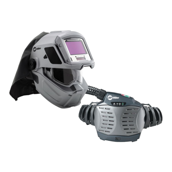
See Section 3 for information on the auto-darkening helmet assembly. The powered air-purifying respirator (PAPR) filters contaminated air and blows it into the welding helmet hood through a flexible connecting hose. The respirator system gener- ates a positive air pressure to help prevent contaminants from entering the hood. -
Page 9: Charging The Battery
POWERED AIR PURIFYING RESPIRATOR 2-2. Charging The Battery Charge battery only with supplied charger in an open, well−ventilated location. Do not allow battery to get wet. Do not attempt to open the battery case. Keep battery away from fire or heat. Charge battery before first use or if battery has not been used for five days. -
Page 10: Installing The Battery
POWERED AIR PURIFYING RESPIRATOR 2-3. Installing The Battery Battery Battery Unlock Button Slide battery into blower body until battery snaps into position. To remove battery, push battery un- lock button down and pull battery from blower assembly. Ref. 805 068 OM-235 936 Page 8... -
Page 11: Installing The Air Filter
POWERED AIR PURIFYING RESPIRATOR 2-4. Installing The Air Filter Do not use the respirator without the spark guard screen, foam prefilter, and particulate (HEPA) filter installed. Replace damaged or dirty air filters. Do not wash filters, clean with compressed air, or reuse dirty air filters. -
Page 12: Attaching The Connecting Hose
POWERED AIR PURIFYING RESPIRATOR 2-5. Attaching The Connecting Hose Ref. 805 068 / 805 098 Screw Connector Tab Connector Be sure connecting hose is properly installed or contami- nated air may enter the hel- met. Connecting Hose To Blower Align pins on hose connector (blower end) with channels in blower recep- tacle. -
Page 13: Operating The Controls
POWERED AIR PURIFYING RESPIRATOR 2-6. Operating The Controls Leave the contami- nated area immediate- ly if the Danger light goes On, the alarm sounds, or the blower vibrates. Do not re- move the equipment until you are in a safe area. -
Page 14: Testing Air Flow
POWERED AIR PURIFYING RESPIRATOR 2-7. Testing Air Flow Always test air flow before using the respirator. Also check air flow each month if respirator is not used regu- larly. Flowmeter Hose Connector (Hood) Disconnect hose from hood. Insert flowmeter into hose. Be sure hose is straight and untwisted. -
Page 15: Testing Air Flow Alarm
POWERED AIR PURIFYING RESPIRATOR 2-8. Testing Air Flow Alarm Always test air flow alarm before using the respirator. Also check air flow alarm each month if respirator is not used regularly. Disconnect hose from hood. Start blower and block air flow by placing your hand over the end of the hose. -
Page 16: Installing Shoulder Strap
POWERED AIR PURIFYING RESPIRATOR 2-9. Installing Shoulder Strap Shoulder Strap Snap Link Connect snaps on shoulder straps to links on belt. 805 068 OM-235 936 Page 14... -
Page 17: Checking The Respirator Before Use
POWERED AIR PURIFYING RESPIRATOR 2-10. Checking The Respirator Before Use 805 068 Before using the respirator, Battery Air flow Alarm check the following items: Turn on blower assembly Verify the battery is fully and check for audible, visu- Air Filter Assembly charged and securely con- al, and vibratory alarms Verify the air filter is suitable... -
Page 18: Putting On The Respirator
POWERED AIR PURIFYING RESPIRATOR 2-11. Putting On The Respirator Do not enter a hazardous area until you are sure the respirator equipment is cor- rectly assembled, working properly, and properly worn. Leave the contaminated area immediately if the Danger light goes On, the alarm sounds, or the blower vi- brates. -
Page 19: Maintenance And Storage
POWERED AIR PURIFYING RESPIRATOR 2-12. Maintenance And Storage Replace damaged or dirty air filters. Do not wash filters, clean with compressed air, or reuse dirty air filters. Never use solvents or abrasive cleaning solutions to clean the respirator. Keep water and other fluids out of blower assembly. - Page 20 POWERED AIR PURIFYING RESPIRATOR Battery run time is too Replace battery. short. Check air filter and replace if necessary (see Sections 2-4 and 2-7). A clogged air filter element reduces battery life. Danger light is On, alarm Continue wearing the respirator and leave the contaminated area sounds or blower vibrates.
-
Page 21: Section 3 − Auto-Darkening Helmet
SECTION 3 − AUTO-DARKENING HELMET See Section 2 for information on the powered air-purifying respirator (PAPR) assembly. 3-1. Specifications Viewing Field 97 x 60mm/3.81 x 2.62 in Reaction Time 0.0000500sec (1/20,000) Available Shades Darkened State: No. 8 − No. 13 / Light State: No. 3... -
Page 22: Helmet Controls
AUTO-DARKENING HELMET 3-2. Helmet Controls Reset Button (See Section 3-3) Low Battery Indicator (See Section 3-3) Variable Shade Control (See Section 3-5) Sensitivity Control (See Section 3-6) Lens Delay Control (See Section 3-4) OTOS OM-235 936 Page 20... -
Page 23: Reset Button And Low Battery Indicator
The low battery indicator lights when 2−3 days of battery life remain. If battery power is low, replace with CR2450 lithium batteries (2 required) (Miller Part No. 217 043) (see Section 3-10). 3-4. Lens Delay Control Lens Delay Control The lens delay control is used to adjust the time for the lens to switch to the clear state after welding. -
Page 24: Variable Shade Control (No. 8 − 13)
AUTO-DARKENING HELMET 3-5. Variable Shade Control (No. 8 − 13) Variable Shade Control (No. 8 − 13) Use the control to adjust the lens shade in the darkened state. Use the table below to select proper shade control setting based on your welding process. -
Page 25: Sensitivity Control
AUTO-DARKENING HELMET 3-6. Sensitivity Control Sensitivity Control Weld Mode Use control to make the lens more respon- sive to different light levels in various weld- ing processes. Use a Mid-Range or 30−50% sensitivity setting for most ap- plications. It may be necessary to adjust helmet sensi- tivity to accommodate different lighting con- ditions or if lens is flashing On and Off. -
Page 26: Adjusting Headgear On Standard Models
AUTO-DARKENING HELMET 3-7. Adjusting Headgear On Standard Models There are four headgear adjust- ments: headgear top, tightness, angle adjustment, and distance adjustment. Headgear Top Adjusts headgear for proper depth on the head to ensure correct bal- ance and stability. Headgear Tightness To adjust, push in the adjusting knob located on the back of the headgear and turn left or right to desired tight-... -
Page 27: Replacing The Lens Covers On Standard Elite Helmets
AUTO-DARKENING HELMET 3-8. Replacing The Lens Covers On Standard Elite Helmets Never use the auto-dark- ening lens without the in- side and outside lens covers properly installed. Welding spatter will dam- age the auto-darkening lens void warranty. Front Lens Gasket Be sure flat side of gasket faces lens cover holder. -
Page 28: Replacing Grinding Shield On Titanium 9400I Helmet
AUTO-DARKENING HELMET 3-9. Replacing Grinding Shield On Titanium 9400i Helmet Never use the auto-dark- ening lens without the in- side and outside lens covers properly installed. Welding spatter will dam- age the auto-darkening lens void warranty. Grinding Shield Retaining Clip Rotate both retaining clips to the Open position. -
Page 29: Replacing The Battery
Replace with CR2450 lithium type batteries (2 required) or equivalent Be sure Positive (Miller Part No. 217043). (+) side of battery Be sure Positive (+) side of the faces up. battery faces up (toward inside of helmet). -
Page 30: Installing Optional Magnifying Lens
AUTO-DARKENING HELMET 3-11. Installing Optional Magnifying Lens Optional Magnifying Lens Starting at the bottom, slide magni- fying lens into the helmet retaining brackets. Align the magnifying lens with the auto-darkening lens as- sembly. D Remove lens holding frame (with auto-darkening lens) from helmet shell. -
Page 31: Troubleshooting
AUTO-DARKENING HELMET 3-13. Troubleshooting Trouble Remedy Auto lens not ON – auto- Check batteries and verify they are in good condition and installed lens will not darken mo- properly. Also, check battery surfaces and contacts and clean if mentarily when the Reset necessary. -
Page 32: Section 4 − Parts List
SECTION 4 − PARTS LIST Î Î 805 193 / Ref. 805 068 Figure 4-1. Powered Air Purifying Respirator (PAPR) w/Standard Elite Helmet OM-235 936 Page 30... - Page 33 Item Part Description Quantity Figure 4-1. Powered Air Purifying Respirator (PAPR) w/Standard Elite Helmet ... . 235671 ..PAPR (Complete System) ......
- Page 34 12 13 Î Î 805 193 / Ref. 805 068 / Ref. 804 111 / 242 385 Figure 4-2. Powered Air Purifying Respirator (PAPR) w/Titanium 9400i Helmet OM-235 936 Page 32...
- Page 35 Item Part Description Quantity Figure 4-2. Powered Air Purifying Respirator (PAPR) w/Titanium 9400i Helmet ... . 247531 ..PAPR (Complete System) ......
- Page 39 LIMITED WARRANTY – Subject to the terms and conditions below. Miller Electric Mfg. Co., Appleton, Wisconsin, warrants to its original retail pur- chaser that the new Miller equipment sold after the effective date of this limited warranty is free of defects in material and workmanship at the time it is shipped by Miller.
- Page 40 Visit our website at www.MillerWelds.com ® Miller Electric Mfg. Co. An Illinois Tool Works Company 1635 West Spencer Street Appleton, WI 54914 USA © ORIGINAL INSTRUCTIONS − PRINTED IN USA 2011 Miller Electric Mfg. Co.
Need help?
Do you have a question about the Powered Air-Purifying Respirator and is the answer not in the manual?
Questions and answers