Table of Contents
Advertisement
Quick Links
Advertisement
Table of Contents
Troubleshooting

Related Manuals for ITT Goulds Pumps 3910


Summary of Contents for ITT Goulds Pumps 3910
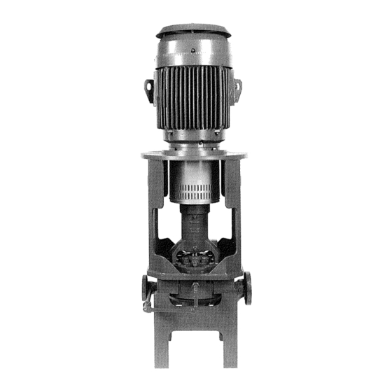
- Page 1 Installation, Operation, and Maintenance Manual Model 3910...
-
Page 3: Table Of Contents
Table of Contents Table of Contents 1 Introduction................................ 4 1.1 Introduction..............................4 1.1.1 Requesting other information ......................4 1.2 Safety ................................ 5 1.2.1 Safety terminology and symbols ..................... 5 1.2.2 Environmental safety........................6 1.2.3 User safety ............................7 1.2.4 Product approval standards ......................9 1.3 Product warranty ............................ - Page 4 Table of Contents 4.6.4 Bypass-piping considerations ....................... 41 4.6.5 Auxiliary-piping checklist ....................... 41 4.6.6 Final piping checklist ........................41 5 Commissioning, Startup, Operation, and Shutdown ................... 42 5.1 Preparation for startup..........................42 5.2 Remove the coupling guard ........................43 5.3 Check the rotation ........................... 44 5.4 Couple the pump and driver ........................
- Page 5 7.1 Operation troubleshooting ........................111 7.2 Alignment troubleshooting........................112 7.3 Assembly troubleshooting ........................112 8 Parts List and Cross-Sectionals ........................113 8.1 Parts list..............................113 9 Local ITT Contacts ............................118 9.1 Regional offices............................. 118 Model 3910 Installation, Operation, and Maintenance Manual...
-
Page 6: Introduction
For instructions, situations, or events that are not consid- ered in this manual or in the sales documents, please contact the nearest ITT representative. Always specify the exact product type and serial number when requesting technical information or spare parts. -
Page 7: Safety
Prohib- ited methods include any modification to the equipment or use of parts not provided by ITT. If there is any uncertainty regarding the appropriate use of the equipment, please contact an ITT representative before proceeding. -
Page 8: Environmental Safety
1.2 Safety Hazard levels Hazard level Indication DANGER: A hazardous situation which, if not avoided, will result in death or seri- ous injury WARNING: A hazardous situation which, if not avoided, could result in death or serious injury CAUTION: A hazardous situation which, if not avoided, could result in minor or moderate injury NOTICE: •... -
Page 9: User Safety
WARNING: If the product has been contaminated in any way, such as from toxic chemicals or nuclear radi- ation, do NOT send the product to ITT until it has been properly decontaminated and advise ITT of these conditions before returning. - Page 10 1.2 Safety Noise WARNING: Sound pressure levels may exceed 80 dbA in operating process plants. Clear visual warnings or other indicators should be available to those entering an area with unsafe noise levels. Per- sonnel should wear appropriate hearing protection when working on or around any equipment, including pumps.
-
Page 11: Product Approval Standards
Use of equipment unsuitable for the environment can pose risks of ignition and/or explosion. Ensure the pump driver and all other auxiliary components meet the required area classifica- tion at the site. If they are not compatible, do not operate the equipment and contact an ITT representative before proceeding. -
Page 12: Ex Considerations And Intended Use
Compliance is fulfilled only when you operate the unit within its intended use. Do not change the condi- tions of the service without the approval of an ITT representative. When you install or maintain explosion Model 3910 Installation, Operation, and Maintenance Manual... - Page 13 Maintenance manual (IOM) can cause serious personal injury or damage to the equipment. This in- cludes any modification to the equipment or use of parts not provided by ITT Goulds Pumps. If there is any question regarding the intended use of the equipment, please contact an ITT Goulds representative before proceeding.
- Page 14 1.4 Ex Considerations and Intended Use Recommended bearing replacement interval (based on L10 life) = 25,000 hours of operation. Equipment for monitoring For additional safety, use condition-monitoring devices. Condition-monitoring devices include but are not limited to these devices: • Pressure gauges •...
- Page 15 If the equipment is Ex certified and the listed temperature exceeds the applicable value shown in Table 1 under SAFETY, then that temperature is not valid. Should this situation occur, please consult with your ITT/Goulds representative. • Cooling systems, such as those for bearing lubrication, mechanical seal systems, etc., where provided, must be operating properly to prevent excess heat generation, sparks and premature failure.
- Page 16 In plants or pumps with cathodic corrosion protection, a small current constantly flows through the construction. This is not permissible on the complete pump or partially-as- sembled machinery without further precautions being taken. ITT should be consulted in this context.
-
Page 17: Transportation And Storage
2 Transportation and Storage 2 Transportation and Storage 2.1 Inspect the delivery 2.1.1 Inspect the package Inspect the package for damaged or missing items upon delivery. Note any damaged or missing items on the receipt and freight bill. File a claim with the shipping company if anything is out of order. If the product has been picked up at a distributor, make a claim directly to the distributor. - Page 18 2.2 Transportation guidelines • Units with drivers mounted can be top heavy. Driver weight could cause the assembled unit to overturn and could result in serious physical injury, or damage to pumps. Table 2: Methods Pump type Lifting method Bare pump without lifting handles Use a suitable sling attached properly to solid points like the casing, the flang- es, or the frames.
-
Page 19: Storage Guidelines
You can purchase long-term storage treatment with the initial unit order or you can purchase it and apply it after the units are already in the field. Contact your local ITT sales representative. 2.3.1.1 Long-term storage If the unit is stored for more than 6 months, these requirements apply: •... -
Page 20: Frostproofing
2.4 Frostproofing 2.4 Frostproofing Table 3: Situations when the pump is or is not frostproof Situation Condition Operating The pump is frostproof. Immersed in a liquid The pump is frostproof. Lifted out of a liquid into a temperature below freezing The impeller might freeze. Model 3910 Installation, Operation, and Maintenance Manual... -
Page 21: Product Description
Use of equipment unsuitable for the environment can pose risks of ignition and/or explosion. Ensure the pump driver and all other auxiliary components meet the required area classifica- tion at the site. If they are not compatible, do not operate the equipment and contact an ITT representative before proceeding. -
Page 22: Nameplate Information
3.2 Nameplate information Seal chamber cover The model 3910 seal chamber cover meets API 682 3rd Edition dimensions for improved performance of mechanical seals. Power end The power end has the following characteristics: • Standard regreasable bearings • Labyrinth seals on the power end •... - Page 23 3.2 Nameplate information Refer to the nameplate on the pump casing for most of the information. See Parts List for item numbers. Nameplate types Nameplate Description Pump casing Provides information about the hydraulic characteristics of the pump. Pump The formula for the pump size is: Discharge x Suction - Nominal Maximum Impeller Diameter in inches.
- Page 24 3.2 Nameplate information Nameplate on the pump casing using metric units Figure 8: Metric units - nameplate on pump casing Figure 9: Nameplate on pump casing using metric units Nameplate field Explanation MODEL Pump model SIZE Size of the pump FLOW Rated pump flow, in cubic meters per hour HEAD...
- Page 25 Use of equipment unsuitable for the environment can pose risks of ignition and/or explosion. Ensure the pump driver and all other auxiliary components meet the required area classifica- tion at the site. If they are not compatible, do not operate the equipment and contact an ITT representative before proceeding.
-
Page 26: Installation
Electrical connections must be made by certified electricians in compliance with all inter- national, national, state and local regulations. • Supervision by an authorized ITT representative is recommended to ensure proper instal- lation. Improper installation may result in equipment damage or decreased performance. 4.1.1 Installation consideration Model 3910 in-line pumps are designed to be mounted directly in the piping. -
Page 27: Installation Consideration
4.1 Pre-installation 4.1.3 Installation consideration Model 3910 in-line pumps are designed to be mounted directly in the piping. The pump casing has a flat base which may be mounted on a concrete foundation which has been poured on a solid footing. 4.1.4 Foundation requirements Requirements •... -
Page 28: Baseplate-Mounting Procedures
4.2 Baseplate-mounting procedures J-type bolts Item Description Baseplate Shims or wedges Foundation Bolt Figure 15: J-type bolts 4.2 Baseplate-mounting procedures 4.2.1 Prepare the baseplate for mounting This procedure assumes you have a basic knowledge of baseplate and foundation design and installa- tion methods. -
Page 29: Install The Baseplate Using Jackscrews
4.2 Baseplate-mounting procedures If you use a pneumatic hammer, make sure that it does not contaminate the surface with oil or other moisture. NOTICE: Do not chip the foundation using heavy tools such as jackhammers. This can damage the structural integrity of the foundation. Remove water or debris from the foundation bolt holes or sleeves. - Page 30 4.2 Baseplate-mounting procedures Item Description Jackscrew Baseplate Foundation Plate Figure 16: Jackscrews Level the driver mounting pads: NOTICE: Remove all dirt from the mounting pads in order to ensure that the correct leveling is achieved. Failure to do so can result in equipment damage or decreased performance. Put one machinist's level lengthwise on one of the two pads.
-
Page 31: Install The Pump, Driver, And Coupling
4.3 Install the pump, driver, and coupling 4.3 Install the pump, driver, and coupling Mount the driver on the motor support. Use applicable bolts and hand tighten. Install the coupling. See the installation instructions from the coupling manufacturer. 4.4 Pump-to-driver alignment Precautions WARNING: •... -
Page 32: Permitted Indicator Values For Alignment Checks
The specified permitted reading values are valid only at operating temperature. For cold set- tings, other values are permitted. The correct tolerances must be used. Failure to do so can result in misalignment. Contact ITT for further information. IMPORTANT •... -
Page 33: Pump-To-Driver Alignment Instructions
4.4 Pump-to-driver alignment Attach one indicator (P) so that the indicator rod comes into contact with the perimeter of the driver coupling half (Y). This indicator is used to measure parallel misalignment. Attach the other indicator (A) so that the indicator rod comes into contact with the inner end of the driver coupling half. - Page 34 4.4 Pump-to-driver alignment Item Description Shims Figure 18: Example of incorrect vertical alignment (side view) 4.4.5.2 Perform angular alignment for a horizontal correction Set the angular alignment indicator (A) to zero on left side of the driver coupling half (Y), 90° from the top-center position (9 o’clock).
- Page 35 The specified permitted reading values are valid only at operating temperature. For cold set- tings, other values are permitted. The correct tolerances must be used. Failure to do so can result in misalignment. Contact ITT for further information. 4.4.5.4 Perform parallel alignment for a horizontal correction Refer to the alignment table in "Permitted indicator values for alignment checks"...
-
Page 36: Grout The Baseplate
4.5 Grout the baseplate Set the parallel alignment indicator (P) to zero on the left side of the driver coupling half (Y), 90° from the top-center position (9 o’clock). Rotate the indicator through the top-center position to the right side, 180° from the start position (3 o’clock). -
Page 37: Piping Checklists
4.6 Piping checklists • Cleaners: Do not use an oil-based cleaner because the grout will not bond to it. See the instructions provided by the grout manufacturer. • Grout: Non-shrink grout is recommended. NOTICE: It is assumed that the installer who grouts the baseplate has knowledge of acceptable meth- ods. - Page 38 4.6 Piping checklists • Risk of serious personal injury or property damage. Fasteners such as bolts and nuts are critical to the safe and reliable operation of the product. Ensure appropriate use of fasten- ers during installation or reassembly of the unit. •...
-
Page 39: Suction-Piping Checklist
4.6 Piping checklists Example: Installation for expansion Correct Incorrect This illustration shows a correct installation for expan- This illustration shows an incorrect installation for expan- sion: sion: Expansion loop/joint 4.6.2 Suction-piping checklist Performance curve reference Net positive suction head available (NPSH ) must always exceed NPSH required (NPSH ) as shown on the published performance curve of the pump. - Page 40 4.6 Piping checklists Check Explanation/comment Checked If more than one pump operates from the This recommendation helps you to achieve a higher same liquid source, check that separate pump performance and prevent vapor locking espe- suction-piping lines are used for each cially with specific gravity of liquid less than 0.60.
- Page 41 4.6 Piping checklists Example: Elbow close to the pump suction inlet Correct Incorrect The correct distance between the inlet flange of the pump and the closest elbow must be at least five pipe di- ameters. Where used, elbows should be long radius. Example: Suction piping equipment Correct Incorrect...
-
Page 42: Discharge Piping Checklist
4.6 Piping checklists 4.6.3 Discharge piping checklist Checklist Check Explanation/comment Checked Check that an isolation valve is installed in The isolation valve is required for: the discharge line. For specific gravity less • Priming than 0.60, minimize distance from pump •... -
Page 43: Bypass-Piping Considerations
When to install a minimum-flow orifice You can size and install a minimum-flow orifice in a bypass line in order to prevent bypassing excessive flows. Consult your ITT representative for assistance in sizing a minimum-flow orifice. When a minimum-flow orifice is unavailable Consider an automatic recirculation control valve or solenoid-operated valve if a constant bypass (mini- mum-flow orifice) is not possible. -
Page 44: Commissioning, Startup, Operation, And Shutdown
5 Commissioning, Startup, Operation, and Shutdown 5 Commissioning, Startup, Operation, and Shutdown 5.1 Preparation for startup WARNING: • Risk of serious physical injury or death. Exceeding any of the pump operating limits (e.g. - pressure, temperature, power, etc.) could result in equipment failure, such as explosion, seizure, or breach of containment. -
Page 45: Remove The Coupling Guard
5.2 Remove the coupling guard Precautions WARNING: The mechanical seal used in an Ex-classified environment must be properly certified. CAUTION: When a cartridge mechanical seal is used, ensure that the set screws in the seal locking ring are tightened and that the centering clips have been removed prior to startup. This prevents seal or shaft sleeve damage by ensuring that the seal is properly installed and centered on the sleeve. -
Page 46: Check The Rotation
5.3 Check the rotation Remove the pump half of the coupling guard: Slightly spread the bottom apart. Lift upwards. Item Description Annular groove Pump-side end plate Driver Pump half of the coupling guard 5.3 Check the rotation WARNING: • Starting the pump in reverse rotation can result in the contact of metal parts, heat genera- tion, and breach of containment. -
Page 47: Coupling Guard Assembly
5.4 Couple the pump and driver WARNING: Failure to disconnect and lock out driver power may result in serious physical injury or death. Always disconnect and lock out power to the driver before performing any installation or main- tenance tasks. •... - Page 48 5.4 Couple the pump and driver Item Description Item Description End plate, drive end 3/8-16 nut, 3 required End plate, pump end 3/8 in. washer Guard half, 2 required 3/8-16 x 2 in. hex head bolt, 3 required Figure 23: Required parts 5.4.1.1 Install the coupling guard Is the end plate (pump end) already installed? •...
- Page 49 5.4 Couple the pump and driver 234B End plate 370N Bearing frame bolts Figure 24: Thrust bearing end cover removal Align the end plate to the thrust bearing end cover so that the two slots in the end plate align with the bolts remaining in the end cover, and the three holes in the end plate align with the holes in the end cover.
- Page 50 5.4 Couple the pump and driver Jackscrew Locations Item Description Pump half of the coupling guard Annular groove Deflector fan guard Driver Figure 25: Coupling guard The annular groove in the guard is located around the end plate. Position the opening (flange) so that it does not interfere with the piping but still allows for access when you install the bolts.
- Page 51 5.4 Couple the pump and driver Thread a nut onto the exposed end of the bolt and tighten firmly. This figure shows the proper sequence of components: Item Description Washer Bolt Item Description Washer Bolt Item Description Driver Coupling guard half Figure 27: Coupling guard Slightly spread the opening of the remaining coupling guard half and place it over the installed cou- pling guard half so that the annular groove in the remaining coupling guard half faces the driver.
- Page 52 5.4 Couple the pump and driver Item Description Annular groove Coupling guard half Driver Figure 28: Coupling guard Place the end plate over the driver shaft and locate the end plate in the annular groove at the rear of the coupling guard half. Model 3910 Installation, Operation, and Maintenance Manual...
- Page 53 5.4 Couple the pump and driver Item Description Annular groove End plate Figure 29: End plate and annular groove Repeat Steps 3 through 5 for the rear end of the coupling guard half, except that you hand tighten the nut. Slide the rear coupling guard half towards the motor so that it completely covers the shafts and cou- pling.
- Page 54 5.4 Couple the pump and driver 5.4.1.2 Install the coupling guard with the optional air cooling package Is the deflector-fan guard support installed? • If yes: Make any necessary coupling adjustments and then proceed to step 2. • If no: Complete the following steps: Remove the spacer portion of the coupling.
- Page 55 5.4 Couple the pump and driver Align the thrust deflector-fan guard support with the thrust bearing end cover so that the sup- port slots align with the holes in the end cover. Replace the thrust bearing end cover and bearing frame screws and torque to values shown in the Maximum torque values for fasteners table.
- Page 56 5.4 Couple the pump and driver Rear coupling guard half Annular groove Deflector fan guard Driver Figure 33: Rear coupling-guard half installation Locate the opening (flange) so that it does not interfere with the piping but does allow access for installing the bolts.
- Page 57 5.4 Couple the pump and driver Item Description Washer Bolt This figure shows an assembled unit: Driver Coupling guard half Figure 35: Assembled unit Slightly spread the opening of the remaining coupling guard half and place it over the installed cou- pling guard half so that the annular groove in the remaining coupling guard half faces the driver.
- Page 58 5.4 Couple the pump and driver Annular groove Coupling guard half Driver Figure 36: Remaining coupling guard half installation Place the end plate over the driver shaft and locate the end plate in the annular groove at the rear of the coupling guard half. Annular groove End plate Figure 37: End plate installation...
-
Page 59: Bearing Lubrication
5.4 Couple the pump and driver 10. Repeat steps 5 through 7 for the rear end of the coupling guard half, except that you hand tighten the nut. Slide the rear coupling guard half towards the motor so that it completely covers the shaft and cou- pling. - Page 60 5.4 Couple the pump and driver 5.4.2.2 Lubricate the bearings with oil WARNING: Risk of explosive hazard and premature failure from sparks and heat generation. Ensure bearings are properly lubricated prior to startup. Fill the oil reservoir in the bearing frame: Fill the bearing chamber through the main body of the Watchdog until it reaches the optimum fluid level visible in the bullseye sight.
-
Page 61: Shaft Sealing With A Mechanical Seal
If the seal has been installed in the pump by ITT, these clips have already been disengaged, however this should be verified by the customer prior to start-up. -
Page 62: Connection Of Sealing Liquid For Mechanical Seals
5.6 Connection of sealing liquid for mechanical seals 5.6 Connection of sealing liquid for mechanical seals Seal lubrication is required Seal faces must have liquid film between them for proper lubrication. Locate the taps using the illustra- tions shipped with the seal. Seal flushing methods Table 8: You can use these methods in order to flush or cool the seal: Method... -
Page 63: Prime The Pump With The Suction Supply Below The Pump
5.7 Pump priming 5.7.2 Prime the pump with the suction supply below the pump Use a foot valve and an outside source of liquid in order to prime the pump. The liquid can come from one of these sources: • A priming pump •... -
Page 64: Start The Pump
5.8 Start the pump 5.8 Start the pump WARNING: Risk of equipment damage, seal failure and breach of containment. Ensure all flush and cool- ing systems are operating correctly prior to starting pump. NOTICE: • Risk of equipment damage due to dry operation. Immediately observe the pressure gauges. - Page 65 5.9 Pump operation precautions NOTICE: • Vary the capacity with the regulating valve in the discharge line. Never throttle the flow from the suction side. This action can result in decreased performance, unexpected heat generation, and equipment damage. • Risk of equipment damage from unexpected heat generation. Do not overload the driver. Ensure that the pump operating conditions are suitable for the driver.
-
Page 66: Shut Down The Pump
5.10 Shut down the pump the pump. Note that different liquids freeze at different temperatures. Some pump designs do not drain completely and may require flushing with a liquid that doesn't freeze. 5.10 Shut down the pump WARNING: Precautions must be taken to prevent physical injury. The pump may handle hazardous and/or toxic fluids. - Page 67 5.12 Dowel the pump casing (optional) • Hardwood block or soft-faced hammer Also make sure that the final alignment is complete. Dowel the pump casing to the baseplate pedestals in order to make sure that you maintain the proper pump position. Drill two holes, one in each casing mounting pad, at the locations provided.
-
Page 68: Maintenance
6 Maintenance 6 Maintenance 6.1 Maintenance schedule Maintenance inspections A maintenance schedule includes these types of inspections: • Routine maintenance • Routine inspections • Three-month inspections • Annual inspections Shorten the inspection intervals appropriately if the pumped fluid is abrasive or corrosive or if the envi- ronment is classified as potentially explosive. -
Page 69: Bearing Maintenance
Cartridge seals installed by the user require disengagement of the hold- ing clips prior to operation, allowing the seal to slide into place. If the seal has been installed in the pump by ITT, these clips have already been disengaged. Other mechanical seal types For other types of mechanical seals, refer to the instructions provided by the seal manufacturer for instal- lation and setting. -
Page 70: Disassembly
6.4 Disassembly Mechanical seal life The life of a mechanical seal depends on the cleanliness of the pumped fluid. Due to the diversity of op- erating conditions, it is not possible to give definite indications as to the life of a mechanical seal. 6.4 Disassembly 6.4.1 Disassembly precautions WARNING:... -
Page 71: Drain The Pump
6.4 Disassembly • Induction heater • Lifting sling • Micrometer • Open end wrenches • Press • Soft face hammer • Spanner wrench • Spanning type puller • • Lifting eyebolt (dependent on pump / motor size) 6.4.3 Drain the pump CAUTION: •... -
Page 72: Remove The Coupling Hub
6.4 Disassembly Remove the back pull-out assembly using a lifting sling through the bearing frame. Figure 43: Lifting sling through bearing frame Remove and discard the casing gasket. You will insert a new casing gasket during reassembly. Remove the jackscrews. Clean all gasket surfaces. -
Page 73: Remove The Impeller (3910Lf)
6.4 Disassembly 122 Shaft 198A Set screw 304 Impeller nut 122 Shaft 198A Set screw 304 Impeller nut Pull the impeller from the shaft. Use a spanning-type puller if required. Remove the impeller key. Save the key for reassembly unless it is damaged. 6.4.7 Remove the impeller (3910LF) CAUTION: Risk of physical injury from sharp edges. -
Page 74: Remove The Seal-Chamber Cover
6.4 Disassembly 443A Impeller capscrew 443A Impeller spacer Shaft Figure 44: Impeller removal Remove the impeller key. Save the key for reassembly unless it is damaged. Remove the impeller spacer. Save the spacer for reassembly unless it is damaged. 6.4.8 Remove the seal-chamber cover Loosen and remove the gland stud nuts. -
Page 75: Remove The Optional Water-Jacket Cover
6.4 Disassembly 370H 360Q Shaft Seal-chamber cover Bearing frame Gland stud nuts 360Q Gland gasket 370H Bearing frame bolts Figure 46: Seal-chamber cover removal Guide the seal-chamber cover over the end of the shaft once the cover releases from the bearing frame. -
Page 76: Disassemble The Power End
6.4 Disassembly 6.4.10 Disassemble the power end This procedure explains how to disassemble purge-oil mist-lubricated power end and includes informa- tion for the disassembly of these optional features: • Pure oil-mist-lubricated power end • Radial-heat-flinger end • Air-cooling package CAUTION: Do not remove bearings from the shaft unless you need to replace them. - Page 77 6.4 Disassembly Shaft 123B Radial deflector fan 123E Thrust deflector fan Deflector set screw Bearing frame Thrust deflector-fan guard 234D Thrust deflector-fan guard support 496Q Support screws Figure 47: Thrust-fan guard support removal Loosen and remove the thrust-bearing end cover and bearing-frame screws. Pry the thrust-bearing end cover thrust deflector out of the bearing frame.
- Page 78 6.4 Disassembly 358E 469P 358E 390C 109A 123A 234A 408I 370N 109A Thrust-bearing end cover Shaft 123A Thrust deflector Bearing frame 358E Oil ring inspection plug 360A Gasket 370N Bearing-frame screw 390C Thrust-bearing end-cover shim 469P Oil ring retainer Figure 48: Thrust bearing end cover removal Model 3910 Installation, Operation, and Maintenance Manual...
- Page 79 6.4 Disassembly Figure 49: Thrust bearing end cover shims Remove and discard the thrust-bearing end-cover shims. For all except SA and MA bearing frames, replace with new shims during reassembly. Remove the two oil ring retainers and the oil ring inspection plugs from the top of the bearing frame. SX, MX, LA, LX, XLA, and XLX pumps have two inspection plugs.
- Page 80 6.4 Disassembly Loosen and remove the thrust-bearing locknut and lockwasher. Press or pull the duplex thrust bearing from the shaft. Press or pull the radial bearing from the shaft. Perform the following based on your pump version: If your pump is... Then...
-
Page 81: Preassembly Inspections
6.5 Preassembly inspections If your pump is... Then... Figure 52: Radial-bearing end cover and radial deflector with gasket (or radial deflector) removal 10. Remove any remaining plugs and fittings. 6.5 Preassembly inspections 6.5.1 Replacement guidelines Casing check and replacement WARNING: Risk of death or serious injury. - Page 82 6.5 Preassembly inspections NOTICE: 3910LF does not have wear rings for case, cover and impeller. Impeller replacement This table shows the criteria for replacing the impeller: Impeller parts When to replace Impeller vanes • When grooved deeper than 1.6 mm | 1/16 in., or •...
- Page 83 6.5 Preassembly inspections Coupling guard replacement Repair or replace the coupling guard if you notice corrosion or other defects. Gaskets, O-rings, and seats replacement WARNING: Risk of death or serious injury. Leaking fluid can cause fire and/or burns. Replace all gaskets and O-rings at each overhaul or disassembly.
-
Page 84: Fastening
6.5 Preassembly inspections 6.5.2 Fastening WARNING: Risk of serious personal injury or property damage. Fasteners such as bolts and nuts are criti- cal to the safe and reliable operation of the product. Ensure appropriate use of fasteners during installation or reassembly of the unit. •... -
Page 85: Wear Rings Inspection And Replacement 3910Lf
6.5 Preassembly inspections • Note any lubricant condition and residue. • Inspect the ball bearings to see if they are loose, rough, or noisy when you rotate them. • Investigate any bearing damage to determine the cause. If the cause is not normal wear, correct the issue before you return the pump to service. - Page 86 6.5 Preassembly inspections 101 Impeller 202 Impeller wear ring 203 Impeller wear ring (No Requirement for 3910LF) Figure 57: Impeller wear ring 125 Seal-chamber throat bushing 184 Seal-chamber cover 230 Seal-chamber cover wear ring Figure 58: Seal chamber cover wear ring When to replace wear rings Replace wear rings when the diametrical clearance exceeds two times the minimum clearance as shown in this table or when the hydraulic performance has decreased to unacceptable levels.
- Page 87 6.5 Preassembly inspections NOTICE: For operating temperatures above 260°C | 500°F and for material with greater galling tenden- cies (e.g. stainless steel), increase diametral clearance dimensions by 0.13 mm | 0.005 in. Table 10: Minimum running clearances Diameter of impeller wear ring Minimum diametrical clearance <50 <2.000 0.25...
- Page 88 6.5 Preassembly inspections Heat the new impeller wear rings to 82° to 93°C | 180° to 200°F using a uniform method for heating, such as an oven, and place them on the impeller wear-ring seats. Item Description 101 Impeller 202 Impeller wear ring 203 Impeller wear ring 320 Set screw Figure 59: Impeller wear ring...
- Page 89 6.5 Preassembly inspections 184 Cover 222E Set screw 230 Seal-chamber-cover wear ring Figure 61: Seal chamber cover wear ring Check the casing wear ring runout and distortion: Measure the bore at each set screw location with inside micrometers or vernier calipers. Correct any distortion in excess of 0.08 mm | 0.003 in.
- Page 90 6.5 Preassembly inspections • Do not machine all wear rings. Spare hard-faced impeller wear rings are supplied to pre-established clearances when both impeller and casing wear rings are renewed. Figure 63: Impeller 10. Install the impeller: Install the impeller key on the shaft of the assembled bearing frame from which the seal-cham- ber cover has been removed, and on which the runouts are within the established specifica- tions.
-
Page 91: Seal-Chamber Cover Inspection And Replacement
6.5 Preassembly inspections 101 Impeller 122 Shaft 202 Casing-side impeller wear-ring 228 Seal-chamber cover side wear ring Figure 64: Impeller wear-ring runout If the impeller wear ring runout is in excess of 0.13 mm | 0.005 in.: Check for distortion at the set screw areas. Check the shaft runout and all mating surfaces of the shaft and impeller hub for perpendicularity. - Page 92 6.5 Preassembly inspections 125 Seal-chamber throat bushing 184 Seal-chamber cover Seal-chamber cover replacement Seal-chamber cover part When to replace Seal-chamber cover surfaces When worn, damaged, or corroded more than 3.2 mm | 0.126 in. deep Inside diameter of seal-chamber cover When the diametral clearance between the bushing and the impeller bushing hub exceeds 1.20 mm | 0.047 in.
-
Page 93: Bearing-Frame Inspection
6.5 Preassembly inspections Chill the new bushing using dry ice or another suitable chilling substance, and install the bush- ing into the cover fit. Tap the bushing in place with a wood block or soft-faced hammer. WARNING: Dry ice and other chilling substances can cause physical injury. Contact the supplier for infor- mation and advice for proper handling precautions and procedures. - Page 94 6.5 Preassembly inspections Surface inspection locations This figure shows the areas to inspect for wear on the bearing frame surface. Figure 67: Surface inspection locations Model 3910 Installation, Operation, and Maintenance Manual...
-
Page 95: Bearing Fits And Tolerances
6.5.8 Bearing fits and tolerances Table 11: Bearing fits and tolerances table (SI units) This table references the bearing fits and tolerances according to ISO 286 (ANSI/ABMA Standard 7) in millimeters | inches. Location Description Tolerance MX, LA LX, XLA inch inch inch... -
Page 96: Reassembly
6.6 Reassembly 6.6 Reassembly 6.6.1 Assemble the frame CAUTION: • Failure to align the gasket with oil grooves will result in bearing failure from a lack of lubri- cation. • Do not over-tighten the thrust-bearing end-cover and bearing-frame screws. • Do not allow the dial indicator to contact the keyway when turning the shaft. - Page 97 6.6 Reassembly Figure 69: Axial end play determination Determine the axial end play as follows: Mount the dial indicator. Use a lever to apply axial force to the impeller end of the shaft and firmly seat the thrust bear- ing against the shoulder in the bearing frame. Apply axial force in the opposite direction and firmly seat the thrust bearing against the thrust- bearing end cover.
- Page 98 6.6 Reassembly If your power Then... end... Has the option- Position the thrust-fan guard support on the thrust-bearing end cover. al air-cooling Install and tighten the thrust-bearing end cover and bearing-frame screws evenly to package torque values shown in the Maximum torque values for 3910 fasteners table. Install the thrust fan over the shaft.
- Page 99 6.6 Reassembly Check Procedure Shaft impeller fit Mount the dial indicator on the bearing frame. Rotate the shaft through a maximum arc from one side of the keyway to the other. If the total indicator reading is greater than 0.050 mm | 0.002 in., determine the cause and correct it.
-
Page 100: Install The Optional Water-Jacket Cover
6.6 Reassembly Check Procedure 10. Install and tighten any plugs and fittings removed during disassembly, including the oil-drain plug, and the sight glass. If your power end has the optional water cooling package, install the finned-tube cooling assembly into the bearing frame. 6.6.2 Install the optional water-jacket cover Install the outer and inner water-jacket-cover O-rings into the grooves in the water jacket cover. -
Page 101: Install The Seal-Chamber Cover
6.6 Reassembly 184 Seal-chamber cover 412S Outer water-jacket-cover O-ring 490 Water jacket cover 497T Outer and inner water-jacket-cover O-ring Figure 71: Optional water jacket cover Lubricate the sealing surfaces in the seal-chamber cover and O-rings with a suitable lubricant. Insert the water jacket cover with O-rings into the fit in the seal-chamber cover. Make sure that the water jacket cover enters uniformly and that the O-rings are not damaged. - Page 102 6.6 Reassembly Shaft Seal-chamber cover Bearing frame Seal-chamber cover wear-ring 370H Bearing-frame bolts Figure 72: Seal chamber cover Set up a sling from the eyebolt to the overhead lifting device. Lift the seal-chamber cover and position it so that it aligns with the shaft. Install the seal-chamber cover on the bearing-frame assembly: Guide the cover carefully over the shaft and into the bearing-frame lock.
- Page 103 6.6 Reassembly Figure 73: Seal-chamber cover face runout Check the seal-chamber cover lock runout: Mount the dial indicator on the shaft. Rotate the shaft so that the indicator rides along the seal-chamber cover lock for 360°. If the total indicator reading is greater than 0.13 mm | 0.005 in., determine the cause and correct it. NOTICE: The impeller and wear-ring clearance setting procedures must be followed.
- Page 104 6.6 Reassembly Figure 75: Seal-chamber cover wear-ring runout Check the seal-chamber face runout: Mount a dial indicator on the shaft. Rotate the shaft so that the indicator rides along the seal-chamber face for 360°. If the total indicator reading is greater than the values shown in this table, determine the cause and correct it.
-
Page 105: Install The Cartridge-Type Mechanical Seal And Seal-Chamber Cover
6.6 Reassembly Figure 76: Seal-chamber face runout Check the seal-chamber lock (register) runout: Mount a dial indicator on the shaft or shaft sleeve. Rotate the shaft so that the indicator rides along the seal-chamber lock (register) for 360°. If the total indicator reading is greater than 0.125 mm | 0.005 in., determine the cause and correct it. Figure 77: Seal-chamber lock (register) runout 6.6.4 Install the cartridge-type mechanical seal and seal-chamber cover NOTICE:... -
Page 106: Determining Impeller Spacer Thickness (Applicable For 3910Lf)
6.6 Reassembly The impeller nut has left-hand threads. Remove the impeller, impeller key, and seal-chamber cover as described in the Disassembly section. Lubricate all O-rings with suitable lubricant, unless the seal manufacturer’s instructions indicate oth- erwise. Slide the cartridge seal assembly (rotary, stationary gland, gland gasket, and sleeve) onto the shaft. NOTICE: Ensure that the mechanical-seal gland-piping connections are properly oriented. -
Page 107: Install The Impeller 3910
6.6 Reassembly With an assembled power end: Attach the seal chamber cover to the bearing frame. Install impeller spacer as supplied between shaft and impeller. Secure impeller to shaft with impeller cap screw or nut. Place indicator on the coupling end of the shaft and zero it out (magnetic base attached to bearing frame). -
Page 108: Install The Coupling Hub
6.6 Reassembly 6.6.8 Install the coupling hub CAUTION: Wear insulated gloves to handle the coupling hub. The coupling hub will get hot and can cause physical injury. NOTICE: If it is necessary to heat the coupling hub due to an interference fit, do not use a torch. Use a heating device such as an oven which uniformly heats the coupling hub. -
Page 109: Post-Assembly Checks
6.6 Reassembly Figure 80: Back pull-out assembly Slide the back pull-out assembly into the proper position in the casing by loosening the jacking bolts evenly. Make sure that the casing gasket is not damaged. Install the casing stud nuts. Inspect the gap between the seal-chamber cover and casing and adjust the casing stud nuts as necessary to make the gap uniform. - Page 110 6.6 Reassembly Construction - API designation The following API designations apply to this table: • • • • • • • S-8N • • • • A-8N • • Modified A-8 (non-API material) 6.6.11.2 Maximum torque values Table 14: Maximum torque values 3910/3910LF Item Description Group / Size...
- Page 111 6.6 Reassembly NOTICE: • The torque values specified in the above table are for lubricated threads. Multiply lubricat- ed value by 4/3 for unlubricated values. • Thread lubricant is required for pressure boundary hardware (Items 353, 355, 356A, & 425). Use nickel-based or molybdenum-based anti-seize compound. •...
- Page 112 6.6 Reassembly • Seal-chamber cover wear ring (230) • Set screws (222E and 320) • Throat bushing - seal-chamber cover (125) • Thrust bearing (duplex pair) (112) • Thrust bearing end-cover gaskets (360A) • Thrust bearing end-cover O-ring (412) • Thrust bearing end-cover shim pack (390C) •...
-
Page 113: Troubleshooting
The shaft is rotating in the wrong direction. Change the rotation. The rotation must match the arrow on the bearing housing or pump casing. The foot valve or suction pipe opening is Consult an ITT representative for the proper not submerged enough. submersion depth. Use a baffle in order to eliminate vortices. -
Page 114: Alignment Troubleshooting
If this does liquid. not help, then contact your ITT representa- tive. The liquid is heavier than expected. Check the specific gravity and viscosity. The stuffing-box packing is too tight. -
Page 115: Parts List And Cross-Sectionals
8 Parts List and Cross-Sectionals 8 Parts List and Cross-Sectionals 8.1 Parts list 3910 Parts list and cross sectional Spares Component Construction ASTM No. Item Start-up 1-2 yr Casing Carbon Steel A216 GR WCB Impeller Carbon Steel A216 GR WCB 109A Thrust Bearing Carbon Steel... - Page 116 8.1 Parts list Spares Component Construction ASTM No. Item Start-up 1-2 yr Deflector-Grease Steel A283 GR D Impeller Nut 316L SS A276 Type 316L Gasket-Casing Spiral Wound –- to SC 316SS Stud-Gland 4140 A193 GR B7 Nut-Gland Stud 4140 A194 GR 2H 356A Note 1 Stud-Casing...
- Page 117 8.1 Parts list Spares Component Construction ASTM No. Item Start-up 1-2 yr 497T (OPT) O-Ring-Water Viton –- Jacket Cover- Inner 540C (OPT) 1 Gasket-Frame to Aramid Fiber –- Cover Model 3910 Installation, Operation, and Maintenance Manual...
- Page 118 8.1 Parts list Model 3910 Installation, Operation, and Maintenance Manual...
- Page 119 8.1 Parts list Model 3910 Installation, Operation, and Maintenance Manual...
-
Page 120: Local Itt Contacts
Vertical Products Operation +1 562-949-2113 +1 562-695-8523 3951 Capitol Avenue City of Industry, CA 90601-1734 Asia Pacific ITT Fluid Technology Asia Pte Ltd +65 627-63693 +65 627-63685 1 Jalan Kilang Timor #04-06 Singapore 159303 Asia Pacific ITT Goulds Pumps Ltd... - Page 121 Visit our website for the latest version of this document and more information: www.gouldspumps.com Goulds Pumps 240 Fall Street Seneca Falls, NY 13148 Form IOM.3910.en-US.2022-11 ©2022 ITT Corporation The original instruction is in English. All non-English instructions are translations of the original instruction.
Need help?
Do you have a question about the Goulds Pumps 3910 and is the answer not in the manual?
Questions and answers