Table of Contents

Related Manuals for Lincoln SKF GVP-S-020-1


Summary of Contents for Lincoln SKF GVP-S-020-1
- Page 1 Installation and operation manual Grease injection lubrication system GVP-S-020-1 Date of issue March 2020 Form number 951-130-450-S020-1 Read manual prior to installation or use of this product. Keep manual nearby for future reference.
-
Page 2: Imprint
Imprint Training courses In order to provide a maximum of safety and economic viability, SKF In accordance with the EU Machine Directive 2006/42/CE, the instal- carries out detailed training courses. It is recommended that the lation and operation instructions are an integral part of a lubrication training courses are attended. -
Page 3: Table Of Contents
Contents Imprint ..............Service . -
Page 4: General
General • rotational direction arrows • fluid connection labels, etc. Meaning of symbols and corresponding must be respected and remain perfectly legible. information It is essential to read these instructions thoroughly and to respect In this manual, the symbols and safety wordings shown on this page the safety instructions given. -
Page 5: Information Concerning The Ec Declaration Of Incorporation
Information concerning the EC Declaration of Incorporation EC Declaration of Incorporation in accordance with EC-Machinery Directive 2006/42/EC, Appendix II Part B The manufacturer SKF France SAS, 204, Bld Charles de Gaulle, B.P. 239 – 37540 St-Cyr-sur-Loire – FRANCE, declares herewith the confor- mity of the partly completed machine Designation: Grease injection lubrication system for chains... -
Page 6: Safety Instructions
1. Safety instructions 1.3 Qualified technical personnel The product described may only be installed, operated, maintained 1.1 General safety instructions and repaired by qualified specialist personnel. Qualified technical personnel are persons who have been trained, assigned and The owner must ensure that safety information has been read by instructed by the operator of the installation. -
Page 7: System Pressure Hazard
1.5 System pressure hazard roller or pin. Product may only be used following the specifications, technical data and limits stated in this manual. Other use or use beyond this purpose is considered unintended. WARNING 1.9 Foreseeable misuse System pressure The product is pressurized during operation. The product A usage of the product differing from the aforementioned conditions must therefore be depressurized before starting assembly, and stated purpose is strictly prohibited. -
Page 8: Lubricants
2. Lubricants NOTE The manufacturer of the bearing or machinery to be lubricated 2.1 General will specify the lubricant requirements for each point to be lubri- cated. You must make sure that the required quantity of lubricant is provided to the relevant lubricating point. If a lubricating point is NOTE insufficiently lubricated, the bearing may become damaged or All SKF products must only be used for their intended purpose and... -
Page 9: Lubricants And The Environment
2.5 Danger relating to lubricants CAUTION Different lubricants must not be mixed together. Doing so can cause damage and require extensive cleaning of the products/centralized lubrication system. To prevent confu- sion, we recommend that you attach information indicating CAUTION the lubricant to be used on the lubricant reservoir. Centralized lubrication systems must be absolutely leak- free. -
Page 10: Design And Function
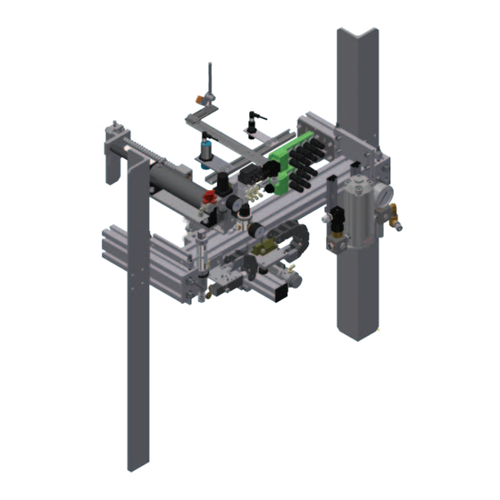
3 Design and function 3.2 Version In general two units are necessary to lubricate chains of an industrial 3.1 Construction conveyor. Each unit is located on one chain side. It is important to pay attention to the GVP unit model in comparison to the chain running The grease injection units type GVP-S-020-1G and GVP-S-020-1D direction. - Page 11 Fig. 1 Overview GVP-S-020-1 1 Inductive proximity sensor 2 Photoelectric sensor 3 Capacitive proximity switch 4 Chain holding system 5 Pick-up system 6 Grease treatment unit 7 Grease inlet 8 Air shut-down safety cylinder 9 Safety end switch 10 Lubricant inlet 11 Lubricant treatment unit 12 Sensor/actuator box...
-
Page 12: Function
3.2 Function The function principle of the grease injection system for the lubrica- tion of conveyor chains is more or less the same for all systems († fig. 2). However some models differ from others by the type of lubrication points, the number of injection heads, etc. - Page 13 GVP-S-020-1 schematic diagram Fig. 3 A - Supply pump Pressure regulating valve Pressure gauge Control solenoid valve Drum pump Manual bleed valve B - Air treatment unit Sectional valve Regulator-filter Pressure switch Pressure gauge C - Lubricant treatment unit Filter Pressure regulating valve Pressure switch Pressure gauge...
-
Page 14: Technical Data
4. Technical data Table 1 Technical data GVP-S-020-1 lubrication system Air feed pressure 5 to 7 bar Lubricant inlet pressure 207 bar max. Injection volume 0,33 ; 0,5 ; 0,75 and 1 cm (factory setting 1 cm Operating temperature 5 to 45 °C Lubricant grease NLGI grade 2 Chain max. -
Page 15: Transport, Delivery And Storage
5.3.3 Storage – general information 5. Transport, delivery and storage • Ensure that no dust gets into stored products by wrapping them in plastic film • Store products on racks or pallets to protect them from damp 5.1 Transport floors •... -
Page 16: Installation Instructions
6. Installation instructions 6.2 Position 6.2.1 Positioning To determine the position of the GVP unit consider the following WARNING factors. All installation, setting, maintenance and repair works on the lubrication system must be carried out only when the Position conveyor is off duty. Working closed to a running conveyor chain may cause operator's injuries and/or important mate- •... - Page 17 6.2.2 Support CAUTION GVP unit must be firmly attached to the support plate to Support or rail to mount the GVP unit must be prepared by customer. prevent any accidental fall. A system fall may damage it or Support or rail must: cause material damage and can also injure the operator or •...
-
Page 18: Outer Connections
6.3 Outer connections Fig. 5 6.3.1 Pneumatic connection The lubrication unit must be connected to the compressed air network. The compressed air quality must comply with purity class 5 defined by DIN ISO 8573-1: • Maximum particle size: 40 μm •... - Page 19 6.3.3 Electric connection Fig. 7 Refer to the electrical documentation supplied with the lubrication unit for information about the electrical connections († fig. 7) to the unit. WARNING Only qualified, instructed specialists who are authorized by the operator may install the electrical connections for the lubrication unit.
-
Page 20: Mechanical Adjustments
6.4 Mechanical adjustments • Loosen the four fastening screws from the flanges († pos. A fig. 9). • Loosen the counter nut († pos. B fig. 9) of the adjustment screw The position of the lubrication unit must be mechanically adjusted to (†... - Page 21 6.4.2 Proximity sensor It is important to correctly position the proximity switches in relation with the lubrication point to guarantee an optimal function. Proximity Proximity switch detects pins/rollers of the moving chain. switches must be perfectly positioned in the axis of point to be When a pin/roller is detected the proximity switch sends a signal to detected (†...
- Page 22 Fig. 10 Sa : 0 < Sa < 0,81 Sn Fig. 11 Détecteur noyable dans le métal objet à détecter Détecteur non noyable dans le métal objet à détecter Fig. 12 Plaquette de mesure Sortie ON Sortie OFF H = course différentielle face sensible Sa = action assurée...
- Page 23 6.4.5 Photoelectric sensor Fig. 13 Photoelectric sensor detects chain pendulum for releasing the chain holding system of the GVP unit. Function Figure 13 The photoelectric sensor detects the pendulum. The chain holding system is released to allow the free running of the pendulum in front of the GVP unit.
-
Page 24: Commissioning
Pin detection 7. Commissioning D1 proximity switch detects pins. During pin lubrication cycle, control unit triggers a lubrication 7.1 General when receiving a signal from D1 proximity switch. Plastic roller detection • Before starting the lubrication unit, check that all outer connec- tions (lubricant supply, air supply, electric connections, etc.) have D2 and D3 proximity switches detect plastic roller. - Page 25 Setting Fig. 17 1 Trigger the limit switch († § 7.5). The carriage will then not move when the different lubrication points are detected. Roller capacitive proximity switch (plastic) 2 Loosen the two counter nuts to bring the switch closer to the roller. As soon as the roller is detected, the LED on the switch lights on.
-
Page 26: Function Test Of Gvp Unit
7.4.2 Lubricant pressure 7.3 Function test of GVP unit The functions of the GVP unit are tested from the AEP3 control unit. The lubricant inlet pressure must not exceed max. 207 bar. Parameters of the lubrication cycle must be set before carrying out 1 Remove the screw plug from the pressure regulator (†... -
Page 27: Limit Switch
7.5 Limit switch The limit switch is fitted at the end position of the injector carriage stroke. It is triggered by the carriage when it overruns the authorized stroke end. The pick-up system is pulled away from the lubrication point, the injector is pulled back and the injector carriage comes back to its initial position. -
Page 28: Modification Of The Injector Metered Volume
7.5 Modification of the injector Fig. 21 metered volume 0,5 cm 1 cm The GVP lubrication system is delivered with a fixed metered volume. It is possible to modify later this metered volume. Four different metered volumes are available: 0,33 ; 0,5 ; 0,75 or 1 cm /stroke. - Page 29 Fig. 24 CAUTION The lubrication system GVP must be disconnected from the power supply and not under pressure when modifying the metered volume. Therefore turn off the power supply and depressurize the system. 1 Check the GVP unit is off and the air supply closed. 2 Loosen the locking nut with an open end wrench (H.19) (†...
-
Page 30: Maintenance
8 Maintenance WARNING The described product may be under pressure when it is being operated. The product must therefore be depressur- ized before starting installation, maintenance, or repair work and before making any changes to the system. NOTE You must not dismantle the product or parts of the product during the warranty period. -
Page 31: Failures
9. Failures WARNING Centralized lubrication systems are under pressure when they are being operated. Centralized lubrication systems Table 3 gives an overview of possible malfunctions and their causes. must therefore be depressurized before starting installation, If you are unable to rectify the malfunction, please contact SKF Ser- maintenance, or repair work and before making any vice Center. -
Page 32: Shutdown
11 Shutdown 12. Spare parts 11.1 Temporary shutdown You can temporarily shut down the described product by disconnect- NOTE ing the electrical, pneumatic, and/or hydraulic supply connections. Only original SKF spare parts may be used. It is prohibited for the For more information, see the section General information in this operator to make alterations to the product or to use non original manual. - Page 33 Table 4 Spare part list GVP-S-020-1 Position Order No. Designation GVP2002-21+924 Air control unit with 3 solenoid valves with base and pressure switch UH2801.08 Grease pressure gauge 0 - 60 bar AC-4261-12B Pressure switch, set at 12 bar (air circuit) GVP432 Injection nozzle head GVP418...
- Page 34 Fig. 28 Spare parts GVP-S-020-1...
- Page 36 Important information on product usage SKF and Lincoln lubrication systems or their components are not approved for use with gases, liquefied gases, pressurized gases in solution and fluids with a vapor pressure exceeding normal atmospheric pressure (1 013 mbar) by more than 0,5 bar at their maximum permissible temperature.
Need help?
Do you have a question about the SKF GVP-S-020-1 and is the answer not in the manual?
Questions and answers