Table of Contents
Advertisement
Quick Links
Advertisement
Table of Contents

Subscribe to Our Youtube Channel
Related Manuals for ICRealtime PTZ-3660SIR


Summary of Contents for ICRealtime PTZ-3660SIR
- Page 1 IR Intelligent Speed Dome User’s Manual Version 1.0.0...
-
Page 2: Table Of Contents
Table of Contents 1 1 1 1 FEATURES AND FUNCTIO FEATURES AND FUNCTIONS FEATURES AND FUNCTIO FEATURES AND FUNCTIO NS................... 1 1 1 1 1 .1 .1 .1 .1 General Introduction General Introduction ..............................1 General Introduction General Introduction Features ..................................1 Features Features Features... - Page 3 3 3 3 3 CABLE CONNECTION CABLE CONNECTION ....................... 9 CABLE CONNECTION CABLE CONNECTION RS485 and Power Cable Connection RS485 and Power Cable Connection ........................9 RS485 and Power Cable Connection RS485 and Power Cable Connection System Layout ................................ 10 3.2.1 BUS connection ..............................
- Page 4 RS485 Bus Main Feature RS485 Bus Main Feature ............................30 RS485 Bus Main Feature RS485 Bus Main Feature RS485 Bus Transmission D RS485 Bus Transmission Distance RS485 Bus Transmission D RS485 Bus Transmission D istance istance istance ........................30 Connection Methods and Terminal Resistance Connection Methods and Terminal Resistance ....................
- Page 5 Welcome Thank you for purchasing our product! This user’s manual is designed to be a reference tool for the operation of your system. Here you can find information about this speed dome features and functions, as well as a detailed menu tree. Please keep it well for future reference! Before installation and operation, please read the following safeguards and warnings carefully!
- Page 6 Important Safeguards and Warnings 1. . . . Electrical safety All installation and operation here should conform to your local electrical safety codes. The power shall conform to the requirement in the SELV (Safety Extra Low Voltage) and the Limited power source is rated 24V AC in the IEC60950-1.
- Page 7 Do not use the volatility solvent such as the benzene or thinner, or detergent with strong abradibility. It may result in lens damage or it may adversely affect the device performance. If there is too much dust, please use the water to dilute the mild detergent first and then use it to clean the device.
-
Page 8: General Introduction
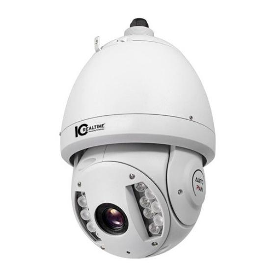
1 1 1 1 Features and Features and F F F F unction unctions s s s Features and Features and unction unction 1.1 General Introduction General Introduction General Introduction General Introduction This series IR intelligent speed dome product is an integrated high intelligent speed dome. It adopts waterproof design and has small and delicate shape. -
Page 9: Auto Touring
Camera scans back and forth regularly in a horizontal field. Here you need to set left and right limit and scan speed. You can set 5 scanning paths. 1.2.7 Auto Touring Add addresses into a routine in a desired order and then set time and stop duration for each address. The dome will begin an auto touring between these addresses. -
Page 10: Intelligent Location
Supports zoom in and zoom out during tilt and pan movement. In this period focus and iris are both in auto mode to get vivid image. 1.2.17 3D Intelligent Location Working with DVR, just click part of the current scene will be displayed in the central window and automatically zooms. -
Page 11: Technical Specifications
All digital design. All data are in the connection board. No data loss when power off occurs. Integrated design, high stability. IR intelligent speed dome max support 255 presets. Support 8 auto touring. Each touring max has 32 presets. Built-in 5 auto scan. - Page 12 Power AC 24V/3A(±20%)(Includes temperature control circuit) Camera Driver Consumption IR Light Consumption ≤20W Decoder Built-in Engine Stepper motor Preset 255( in PELCO protocol) Auto Tour Auto Pattern Auto Scan Privacy Mask Maximum 24 zones Information Address, dome title, dome coordinates, temperature and etc. Lens Adjust speed in accordance with lens Auto Rotation...
-
Page 13: Protocol, Baud Rate, Address Setup Protocol, Baud Rate, Protocol, Baud Rate, Address Setup Address Setup
2 2 2 2 Protocol Protocol, , , , B B B B aud aud R R R R ate ate, , , , A A A A ddress ddress setup setup Protocol Protocol ddress ddress setup setup Before you operate, you need to set protocol, baud rate and address. Otherwise you can not control the product! 2.1 Protocol and Protocol and... -
Page 14: Set Address Dial Switch
Please refer to the protocol sheets for detailed information. Reserved Baud rate Parity Connect to the 120 Please note the speed dome cans automatically recognize the DH-SD, PELCO-D. PELCO-P. Usually you do not need to set. Please refer to the baud rate sheet for detailed information. Baud Rate 9600bps 4800bps... - Page 15 …… …………………………………………………………………...
-
Page 16: Cable Connection Cable Connection
3 3 3 3 Cable Connection Cable Connection Cable Connection Cable Connection 3.1 RS485 and RS485 and P P P P ower ower C C C C able able C C C C onnection onnection RS485 and RS485 and ower ower able able... -
Page 17: System Layout
Right now the device does not support this function. Reserved audio port. Audio connection port. Right now the device does not support this function. VIDEO Ground port. Video output port. Power port connection interface is shown as in Figure 3-3. Figure 3-3 Name Function... -
Page 18: Star Connection
Figure 3-5 Note: Please use shielded twisted pair. The shielded layer shall connect to GND firmly; otherwise it may affect communication or video work. 3.2.2 Star Connection Please refer to Figure 3-6 for start connection information. Figure 3-6 3.3 Keyboard Connection This series dome supports keyboard operation. - Page 19 protocol. The most direct and easy way is to use current system to process video signal and add some control keyboards to control speed dome. See Figure 3-8. Figure 3-8...
-
Page 20: Menu
4 4 4 4 Menu Menu Menu Menu 4.1 Screen Menu Index Note: ERR means current setup is invalid. Please restore factory default setup. Slight difference may be found in the parameter interface due to different product series. . SYSTEM INITIAL INFORMATION…... -
Page 21: Self
The above diagram illustrates the overall structure of the speed dome setup menu. Note: ERR means current setup is invalid. Please make sure all the cable connections are right. 4.2 S S S S elf elf elf elf- - - - diagnosis S diagnosis S diagnosis System diagnosis S... -
Page 22: Menu Operation
bright, IR light compensation and etc. : Log out the system menu. EXIT 4.4 Menu Operation In the speed dome main menu, you can use the left/right button on the keyboard or in the speed dome terminal menu to configure the system menu. Before setup, please move the cursor to the current item you want to configure. -
Page 23: Display Setting
4.4.1.2 Address Information ADDR TYPE : HARD ADDR-HARD : 001 ADDR-SOFT : 001 BACK EXIT Move the cursor to SITE INFORMATION and then click confirm button. ADDR TYPE: There are two options: soft and hard. Please use the left/right button on the keyboard or in the speed dome terminal menu to set. - Page 24 WB SETTING EXPOSURE SETTING DAY/NIGHT SETTING :AUTO FOCUS MODE FOCUS LIMIT : 30CM ZOOM SPEED : 08 DIGITAL ZOOM : OFF APERTURE : 09 NEXT PAGE BACK EXIT Move the cursor to CAMERA SETTING and then click confirm button, you can go to the submenu. WHITE BALANCE SETUP: It is to set the camera white balance mode.
- Page 25 AE MODE : AUTO :ON/OFF GAIN SETTING : 02 GAIN LIMIT : 08 SHUTTER : 1/50 SLOW SHUTTER LIMIT : 1/12 IRIS SETTING : 11 NOISE REDUCTION : 03 EXPOSURE COM : 08 3D NOISE CONTROL : ON/OFF SLOW AE : 01 BACK SLOW SHUTTER...
- Page 26 GAIN LIMIT: It is to control the camera gain. The video noise may be too high if the gain value is large in the low illumination. SLOW SHUTTER LOW LIMIT: It is to set the camera slow shutter. If the shutter time is too long, it may affect the video real-time feature.
-
Page 27: Function Setting
BACK: Go back to previous menu. EXIT: Log out system menu. Slight difference may be found due to different IR intelligent speed dome series. 4.4.4 Function Setting PRESET AUTO SCAN AUTO CRUISE AUTO PATTERN IDLE MOTION PRIVACY MASKING NEXT PAGE BACK EXIT Please go back to main menu and move the cursor to FUNCTION SETTING, click confirm button. - Page 28 TITLE:Title text is the label used for you to identify the camera. System will automatically name a title for the camera. SETTING: Please input preset number first and then select the monitor zone. Please move the cursor to setting and click confirm button. The system will pop up a message: PRESET: ***. Here *** means preset number.
- Page 29 SCAN NO:Here is to set auto scan number. The value ranges from 1 to 5. Please use the left/right button on the keyboard or in the speed dome terminal menu to set. SET LEFT LIMIT:Here is to set camera left address. Click confirm button to save current setup. SET RIGHT LIMIT:Here is to set camera right address.
- Page 30 DELETE CRUISE:Here is to delete a cruise. Input cruise number in CRUISE NO and then move the cursor to DELETE cruise, click confirm button to delete. CALL: Here is to activate cruise. Input touring number in touring NO and highlight CALL, click confirm button to activate touring.
- Page 31 Please make sure you current camera supports this function. :001 PRIVACY ACTIVATE : OFF RESIZE : ↑ DELETE SAVE BACK EXIT Move the cursor to PRIVACY ZONE and click confirm button, system goes to privacy mask setup interface. The zone amount may vary due to different series product. Note: For security reasons, please set privacy zone a little bit larger than the privacy object size.
- Page 32 :OFF IDLE FUNC :010MIN IDLE TIME :PRESET IDLE ACTION :001 PRESET NO AUTO SCAN NO :001 :001 CRUISE NO PATTERN NO :001 SAVE BACK EXIT When there is no available command for specified time, dome automatically goes on the previous set functions.
-
Page 33: Ir Light Setup
• MENU IDLE: If current setup is ON, once you open the menu and leave it idle for specified period, the menu may automatically disappear. If current setup is OFF, the menu is always there and will not disappear. Please use the left/right button to set. The option includes 1m/2m/3m/4m/5m/off.The default value is 1 minute. -
Page 34: Dome Abnormal Phenomenon Operation
IR SENSITIVITY: 4 IRLIGHT CTRL: ZOOM PRI NEAR LIGHT: 50 FAR LIGHT: 50 IRLIGHT COMP: 03 BACK EXIT Move the cursor to highlight IR LIGHT SETTING button and then click confirm button. IR SENSITIVITY: Here you can enable the IR light sensitivity function. SWITCH ZOOM: It is the zoom rate of the near light, and far light. -
Page 35: Faq Faq
5 5 5 5 FAQ 5.1 Daily Maintenance Please clean dome cover regularly to get vivid image. Handle the cover with care. Use water to wash. Don’t use cloth to clean. Use mild detergent to clean if there is too much dust. Note: The sweat from your hand may erode plating surface, your nail may scrape dome cover result in blur image. -
Page 36: Appendix Ⅰ Ⅰ Ⅰ Ⅰ Thunder Proof And Su Appendix Appendix Thunder Proof And Su Thunder Proof And Surge Protection Thunder Proof And Su Rge Protection
6 6 6 6 Appendix Ⅰ Appendix Ⅰ Thunder Proof and Surge Protection Thunder Proof and Surge Protection Appendix Ⅰ Appendix Ⅰ Thunder Proof and Surge Protection Thunder Proof and Surge Protection This series speed dome adopts TVS lighting protection technology. It can effectively prevent damages from various pulse signals below 1500W, such as sudden lighting and surge. -
Page 37: Appendix About Rs485 Bus
7 7 7 7 Appendix Appendix Ⅱ Ⅱ Ⅱ Ⅱ About RS485 B About RS485 Bus Appendix Appendix About RS485 B About RS485 B us us 7.1 RS485 Bus Main Feature RS485 Bus Main Feature RS485 Bus Main Feature RS485 Bus Main Feature RS485 is semi duplex communication cable of impedance 120Ω. - Page 38 conform to RS485 Bus standard. When the distances between devices are too long, the signal reflection occurs and anti-jamming decreases, thus the signal reliability becomes very low. You can see speed dome is not under control or speed dome is running automatically and can not stop. Figure 7-3 In this situation, we recommend RS485 distributor.
- Page 39 8 8 8 8 Appendix Appendix Toxic or Hazardous Materials or Elements Toxic or Hazardous Materials or Elements Appendix Appendix Toxic or Hazardous Materials or Elements Toxic or Hazardous Materials or Elements Toxic or Hazardous Materials or Elements Component Name Cr VI PBDE Sheet Metal...
Need help?
Do you have a question about the PTZ-3660SIR and is the answer not in the manual?
Questions and answers