Sign In
Upload
Download
Table of Contents
Contents
Add to my manuals
Delete from my manuals
Share
URL of this page:
HTML Link:
Bookmark this page
Add
Manual will be automatically added to "My Manuals"
Print this page
×
Bookmark added
×
Added to my manuals
Manuals
Brands
Unical Manuals
Boiler
IVEN 04 RTN 24
Installation, use and maintenance manual
Unical IVEN 04 RTN 24 Installation, Use And Maintenance Manual
Hide thumbs
1
2
3
Table Of Contents
4
5
6
7
8
9
10
11
12
13
14
15
16
17
18
19
20
21
22
23
24
25
26
27
28
29
30
31
32
33
34
35
36
page
of
36
Go
/
36
Contents
Table of Contents
Bookmarks
Table of Contents
Table of Contents
Technical Features
Dimensions
Hydraulic Circuits
Directions for
Installers
Installation
Packing
Positioning the Boiler
Assembling the Boiler
Ventilation
Flue Gas Discharge System
Positioning of Terminals for Type C Boilers
Flue Gas Discharge and Air Suction with Separate
Measurements of Combustion Efficiency
Connection to the Gas Mains
Hydraulic Connection
Electrical Connection
Jumper Location
Filling the System
Starting the Boiler
Adjusting the Burner
Modification of Other Gases
Finding Chart and Corrective Actions
Failure Code
Users' Instruction
Control Panel
Switching On/Off
Antifrost Protection
Important Suggestion and Notes
Advertisement
Quick Links
Download this manual
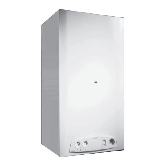
IVEN
04
RTN 24 - RTFS 24 - RTFS 28
CTN 24 F - CTFS 24 F - CTFS 28 F
INSTALLATION USE
AND MAINTENANCE
00331967 - 1
edition - 02/2004
a
Table of
Contents
Previous
Page
Next
Page
1
2
3
4
5
Advertisement
Table of Contents
Need help?
Do you have a question about the IVEN 04 RTN 24 and is the answer not in the manual?
Ask a question
Questions and answers
Related Manuals for Unical IVEN 04 RTN 24
Boiler Unical INOXIA GJ Series Installation And Servicing Manual
(56 pages)
Boiler Unical IVEN 04 CTFS 24 F Installation, Use And Maintenance Manual
(36 pages)
Boiler Unical IDEA AB 24 Installation And Servicing Manual
(72 pages)
Boiler Unical IDEA AC 23 Installation And Servicing Manual
(72 pages)
Boiler Unical EVE 05 RTN 24 Installation, Use And Maintenance Manual
(36 pages)
Boiler Unical GHISS 16R AP PV User Manual
Standard gas device with cast-iron segmented heatexchanger, with direct spark ignition (ae), and piezo ignition (ap) (33 pages)
Boiler Unical PK 150 X 2S Installation And Servicing Instructions
(52 pages)
Boiler Unical ALKON 50 kW Installation And Servicing Manual
(64 pages)
Boiler Unical Lattner ALKON 50 Installation And Servicing Manual
Condensing gas boiler (52 pages)
Boiler Unical Tristar 2S Installer And Maintenance Technician Instructions
(52 pages)
Boiler Unical ALKON 24 B 60 Installation And Servicing Manual
(44 pages)
Boiler Unical Alkon Cargo 35 Installation Manual
(48 pages)
Boiler Unical DUA plus Installation And User Instruction Manual
(32 pages)
Boiler Unical ALKON 35S R User Operating Instructions Manual
(8 pages)
Boiler Unical KON User Operating Instructions Manual
(41 pages)
Boiler Unical Kone R 24 User Operating Instructions Manual
(41 pages)
This manual is also suitable for:
Iven 04 rtfs 24
Iven 04 rtfs 28
Iven 04 ctn 24 f
Iven 04 ctfs 24 f
Iven 04 ctfs 28 f
Table of Contents
Print
Rename the bookmark
Delete bookmark?
Delete from my manuals?
Login
Sign In
OR
Sign in with Facebook
Sign in with Google
Upload manual
Upload from disk
Upload from URL


Need help?
Do you have a question about the IVEN 04 RTN 24 and is the answer not in the manual?
Questions and answers