
Related Manuals for Unical Alkon Cargo 35


Summary of Contents for Unical Alkon Cargo 35
- Page 1 ALKON CARGO 35 INSTALLATION AND SERVICING MANUAL 00332603 - 2 edition - 04/2008...
-
Page 2: Table Of Contents
The end user MUST not make any alterations to the boiler. Failure to follow the instructions indicated in this manual, which is supplied with the boiler, could cause injury to persons, animals or damage to property. UNICAL shall not be held liable for any injury and/or damage. -
Page 3: General Information
Any other use of this appliance will be considered improper. UNICAL declines any responsibility for any damages or injuries caused by an improper use; in this case the risk is completely at the user’s responsibility. -
Page 4: Safety Warnings
Servicing or repairs of the appliance must be carried out by competent qualified service technicians; UNICAL recommends drawing up a service contract. Bad or irregular servicing could compromise the safe operation of the appliance, and could cause injury to persons, animals or damage to property for which UNICAL shall not be held liable. -
Page 5: Data Badge
General information 1.6 - DATA BADGE The data badge is situated on the inside of the right hand side panel of the boiler’s casing. CE Marking The CE marking documents that the boilers satisfy: The essential requirements of the Directive regarding gas appliances (Directive 90/396/CEE) The essential requirements of the Directive regarding electromagnetic compatibility (Directive 89/336/CEE) -
Page 6: General Warnings
Any repairs must be carried out solely by Unical authorized Keep this manual in a safe place for future reference. technicians and using only original spare parts. Non-obser-... -
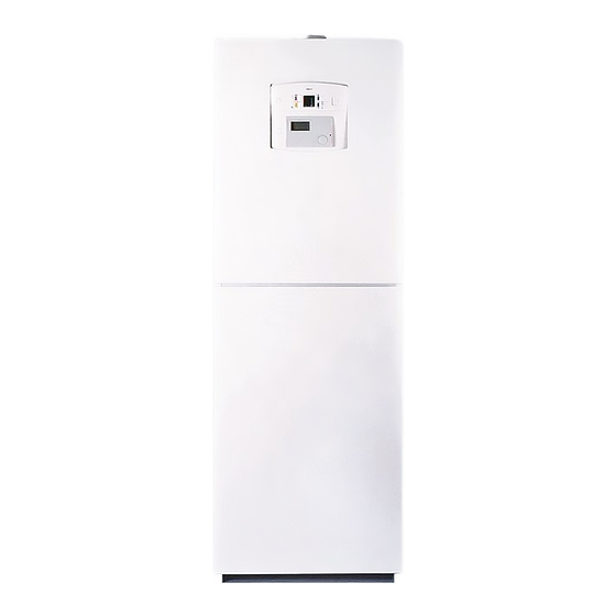
Page 7: Technical Features And Dimensions
• Primary silicon aluminium heat exchanger; • 150 litre enamelled vertical storage tank with an helicoidal The ALKON CARGO 35 boilers are room sealed gas fired heat exchanger units with an atmospheric fully pre-mixed burner. • Control and management microprocessor;... -
Page 8: Dimensions
Technical features and dimensions 2.2 - DIMENSIONS System flow mixed zone control 1 System flow direct zone control System flow mixed zone control 2 (optional) System return mixed zone control 1 System return direct zone control System return mixed zone control 2 (optional) Gas inlet DHW outlet Cold water inlet... -
Page 9: Main Components
Technical features and dimensions 2.3 - MAIN COMPONENTS Manifold distributor Concentric adaptor Air vent valve DHW expansion Overheat limit vessels thermostat Modulating fan Heat exchanger System pressure Automatic air vent sensor Gas valve 3-way valve motor Modulating pump Manifold flow Diverter valve motor Mixed zone control Condensate... -
Page 10: Boiler Water Circuit
Technical features and dimensions 2.4 - BOILER WATER CIRCUIT Manifold return Non return valve Motorized mixing valve Mixing zone control circulation pump Return sensor zone 1 Direct zone pump Mixing header discharge valve Primary circuit modulating pump CH return sensor 10 Boiler sensor 11 Mixing header 12 Air vent... -
Page 11: Performance Data According To The Standard Uni 10348
PERFORMANCE DATA ACCORDING TO STANDARD UNI 10348 For information regarding the adjustment of: INJECTORS - BURNER PRESSURES – DIAPHRAGMS – OUTPUTS – GAS CONSUMPTIONS please refer to the paragraph BURNER ADJUSTMENT. ALKON CARGO 35 Heat input 34,8 Nominal heat output... -
Page 12: Instructions For The Installer
Instructions for the installer INSTRUCTIONS FOR THE INSTALLER 3.1 - GENERAL WARNINGS WARNING! In rooms where aggressive vapours or dust WARNING! is present the appliance must operate inde- This boiler has to be destined for the use pendently from the air present in the boiler’s for which it has been expressively designed location room! for. -
Page 13: Standard Codes For Installation
Keep the packaging material (wooden cage, nails, plastic bags, polyester protection etc.) out of the reach of children as they can be dangerous. UNICAL refuses all liability for injury to persons, 1904 animals or damage to property deriving from not having respected the above mentioned recommendations. -
Page 14: Boiler Location
Instructions for the installer 3.4 - BOILER LOCATION - The appliance must be installed exclusively on a vertical When selecting the position for the installation of the boiler and solid wall, capable of adequately supporting the weight please comply to the following safety requirements: - Fit the appliance in rooms protected from frost of the boiler - In rooms where aggressive vapours or dust are present, the... -
Page 15: Gas Connections
Instructions for the installer As a safety measure against gas leaks, Unical 3.5 - GAS CONNECTION recommends installing a surveillance and pro- tective system composed of a gas leakage DANGER! detector combined with an on-off selenoid The gas connection must be carried out only valve fitted on the gas supply line. -
Page 16: Central Heating Connections
Instructions for the installer 3.6 - CENTRAL HEATING CONNECTIONS When determining the size of the CH circuit pipes it is essential to bear in mind the pressure losses induced by the radiators, any eventual thermostatic radiator valves, lockshield valves WARNING! and by the heating system’s layout. -
Page 17: Dhw Connections
Instructions for the installer 3.7 - DOMESTIC HOT WATER Note: The pressure in the system must be CONNECTIONS between 1 and 3 bar (if the pressure is higher fit a reducing pressure valve). WARNING! Before connecting the boiler to the water mains supply ensure that the system is WARNING! flushed out with a suitable product in order... -
Page 18: Condensate Drain Outlet
Instructions for the installer 3.9 - CONDENSATE DRAIN During the combustion process the boiler produces conden- sate which, through the “A” pipe, flows into the siphon. The condensate which forms inside the boiler has to be routed into an adequate drain by means of the pipe “B”. DANGER! Before commissioning the appliance fill the siphon and check the correct drainage of the... -
Page 19: Flue Outlet Connections
The two terminals must not be fitted on to two opposite and national Standards (refer to Standard UNI-CIG 7129, point walls. 4 and UNI-CIG point 5) We recommend using only original UNICAL flue outlet systems. Damages caused by installation errors and for non-observance of the instructions given by the same manufacturer will invalidate all the supplier’s contractual or extra contractual re-... - Page 20 Instructions for the installer FLUE OUTLETS WITH CONCENTRIC DUCTS Ø 60/100 mm Important: the outlet/inlet flue has to Type C13 have a minimum inclination of 3% The minimum allowable length of the horizontal concentric pi- towards the top in the outlet direction, pes is of 0,75 metres.
- Page 21 Instructions for the installer FLUE OUTLETS WITH CONCENTRIC DUCTS Ø 80/125 mm Important: the outlet/inlet flue has to Type C13 have a minimum inclination of 3% The minimum allowable length of the horizontal concentric pi- towards the top in the outlet direction, pes is of 0,75 metres.
- Page 22 Instructions for the installer FLUE OUTLET WITH SEPARATE DUCTS Ø 80 mm The maximum pressure loss permitted, independently from the type of installation, must not exceed the value of 100 Pa. 303,5 12,5 Ø 80 TSC0130C TSC0150C KIT5780C KIT5770C 00361435 It is not permitted to position the two termi- nals on opposite walls.
- Page 23 - For the vertical flue outlet duct Ø 80 L=1 the pressure loss is of 8 Pa. Note: These values refer to flue systems made with original UNICAL non flexible and smooth pipes. Verification Example n°1: twin flue pipe adaptor ..........
-
Page 24: Electrical Connections
UNICAL refuses responsibility for any damages arising from Access to the electrical terminal strip and failure to earth the boiler correctly. - Page 25 Instructions for the installer If connecting a thermostat, use one of the extractable grommets which are present on the electrical panel, carrying out the following operations: - Remove the grommet 1 - Unscrew the ring nut 2 - Remove the plastic ‘tap’ 3 - Insert the cable 4 - Wire the electrical connections onto the terminal strip...
- Page 26 Instructions for the installer 3.11 - PRACTICAL WIRING DIAGRAM E.ACC./RIL. LEGEND: A1...A13 = Service connectors E.ACC = Ignition/detection electrode = Diverter valve motor = Mixing motor valve zone 1 = Mixing motor valve zone 2 (optional) TRASF. = Pump direct zone ACC.
- Page 27 Instructions for the installer TA Zone 1 TA Zone 2 E8 HEATING CONTROLLER BROWN Mains supply YELLOW/GREEN 230 V - 50 Hz LIGHT BLUE 2 3 6 2 3 6 BLUE YELLOW/GREEN YELLOW/GREEN...
-
Page 28: Filling The System
Use the pressure gauge fitted on normal boiler operation. the boiler to read the system’s pressure value. UNICAL refuses all liability for injury to per- sons, animals or damage to property deri- NOTE! ving from not having respected the above If the boiler has not been fired for a long period mentioned recommendations. -
Page 29: Initial Lighting
Failure to do so could in case the boiler is sited in a cupboard compartment or in cause injury to persons, animals or damage to property. UNICAL shall not be held liable a narrow space. for any injury and/or damage. -
Page 30: Burner Pressure Adjustment
3.14 - BURNER PRESSURE ADJUSTMENT WARNING! All the instructions indicated below are for the exclusive use of qualified UNICAL service te- chnicians or installers. All the boilers leave the factory already calibra- ted and tested. If it is necessary to change the... - Page 31 Instructions for the installer If necessary correct the value by turning the adjustment C) COMPLETION OF THE BASIC screw “B” in a CLOCKWISE direction to increase the va- ADJUSTMENTS lue and in an ANTICLOCKWISE direction in order to de- crease it. Check the C0 values at the minimum and maximum ou- tput...
-
Page 32: Gas Conversions
Instructions for the installer 3.15 - GAS CONVERSION To convert the boiler for use with another type of gas the The boilers are manufactured for use with the type of gas following steps must be carried out: specifically requested when ordered. 1. -
Page 33: Programming The Operating Parameters
Instructions for the installer 3.16 - PROGRAMMING OF THE OPERATING PARAMETERS WARNING! THESE OPERATIONS ARE ACCESSIBLE ONLY TO TRAINED INSTALLERS AND SERVICE ENGINEERS FOR INSPECTION AND EVENTUAL CHANGES OF THE PARAMETER SETTINGS Press down the YELLOW and LIGHT BLUE key (Operation C) simultaneously to enter in the service menu SE, which will After setting the desired value pressing the YELLOW key stores... - Page 34 Instructions for the installer MODULATING PUMP MODULATING CAPACITY MAXIMUM HEATING TEMPERATURE SETTING Continue to change the parameters by pressing the – key Continue to change the parameters by pressing the – key (decrease). (decrease). The successive parameter which can be changed is: The successive parameter which can be changed is: MAXIMUM MODULATING PUMP MODULATING CAPACITY (Pr).
-
Page 35: Description Of The Heating Controller's Operating Menus And Operating Levels
Instructions for the installer 3.17 - DESCRIPTION OF THE E8 HEATING CONTROLLER’S MENUS AND OPERATING LEVELS For further information please refer to the “USERS INSTRUCTIONS” supplied with the E8.5064 heating controller. LEVELS MAIN AREAS MENU The settings in the different areas are divided into operating General levels: Value selection summary... -
Page 36: Commissioning Procedure
Instructions for the installer 3.18 - COMMISSIONING PROCEDURE CHECKING THE SENSORS AND RELAYS ELECTRICAL CONNECTIONS 1. CHECKING THE SETTINGS • Check that the electrical connections on the heating con- • Fit controller, make electrical connections and fire boiler. troller have been carried out correctly, according to the type of installation chosen, as indicated in section 3.2.1. - Page 37 Instructions for the installer Relay TEST Sensor TEST - Start the RELAY TEST by pressing the programming key. - Start the SENSOR TEST by pressing the programming By turning the rotary knob in a clockwise direction you can key. By turning the rotary knob in a clockwise direction you select the RELAYS ( from 1 to 11) –...
-
Page 38: Hot Water
Instructions for the installer TEMPERATURE AND HEATING SLOPE SETTINGS By turning the rotary knob in a • Open the panel cover on the controller, turn the rotary knob clockwise direction you gain access in a clockwise direction, search for the USER area menu. to the HEATING CIRCUIT 1 Heat circuit i ®... - Page 39 Instructions for the installer Heat circuit I Note: (**) If necessary personalize the Designation Value range Default HEATING SLOPE parameter. MAX T-FLOW 20°C – 110° C 80 °C MIN T-FLOW 10°C – 110°C 10 °C 100,0 FROST PROT ——; 0 °C (-15)°C –...
-
Page 40: Maintenance And Servicing Schedule
Instructions for the installer CIRCL TIME Program for circulation pump 1 ON 20§ C HOTW-PROG (*) Program for hot water charging pump HTG-PROG 1 1st heating program for first controller heating circuit HTG-PROG 2 2nd heating program for first controller heating circuit 1 OFF 20§... -
Page 41: Servicing Schedule
• Remove the appliance’s front panel. For this reason UNICAL recommends that a servicing contract should be made with one of our authorized After having carried out all the necessary maintenance work After Sales Service Assistance Centre. - Page 42 Inspection and servicing schedule Check Recommended servicing operations annually Examine all water seal components for soundness Test for gas soundness Check the water and gas safety devices Clean the combustion circuit heat exchanger/body Clean the burner and check the ignition efficiency Clean the fan Check efficiency of fan's operation Check the gas flow rate and eventual gas adjustment...
-
Page 43: Fault Finding
Fault finding When the fault signalling led (1) is illuminated, press the LI- FAULT FINDING GHT BLUE key (2) to check the error code on the display (3). 5.1 - ERROR CODES The boiler is fitted with an integrated diagnostic readout whi- ch, in case of malfunction, consents the immediate individua- tion of the type of fault directly from the control panel display. -
Page 44: Servicing Request
Fault finding 5.3 - DISPLAY OF ERROR CODES ON E8 Code: Description: HEATING CONTROLLER Alteration of the factory parameters caused by electromagnetic disturbances Corrective action: Restore the factory parameters Description: Code: Flame detected before the start of the ignition cycle Corrective action: emove detection electrode wiring from the control If a fault or error occurs in the heating system a blinking warning... - Page 45 Fault finding Code: Description: Code: Description: Bad water circulation Heating sensor failure (SR) E 40 E 12 Corrective action: Corrective action: Examine the system Check the sensor’s efficiency and/or wiring Description: Code: Water temperature too high detected by the CH Code: Description: sensor (SR) (>95°C)
- Page 46 NOTE: ........................................................................................................................................................................................................................................................................................................................................................................................................................................................................................................................................................................................................................................................................................................................................................................................................................................................................................................................................
- Page 47 NOTE: ........................................................................................................................................................................................................................................................................................................................................................................................................................................................................................................................................................................................................................................................................................................................................................................................................................................................................................................................................
- Page 48 - info@unical-ag.com The Unical declines every responsibility for the possible inaccuracies if owed to errors of transcript or press. Also reserves the right to bring those changes that it will hold necessary to it own products or profits, without jeopardizing its essential characteristics.
Need help?
Do you have a question about the Alkon Cargo 35 and is the answer not in the manual?
Questions and answers