ZOLL R Series In-Service Manual
Hide thumbs
Also See for R Series:
- Service manual (548 pages) ,
- Operator's manual (88 pages) ,
- Manual (35 pages)
Table of Contents
Advertisement
Quick Links
R Series ALS In-service Guide
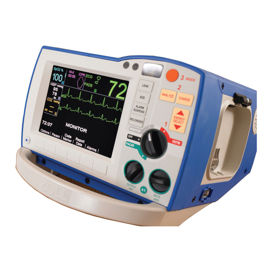
OVERVIEW
Color Coded Operating System:
•
Review with the Mode Selector dial.
RED
o
GREEN
o
GREY
o
Power Indicators
•
Battery Indicator
GREEN
o
AMBER
o
o FLASHING = Problem (check battery)
o Indicator lights on battery show 30 min. increments
for a total of 4 hours of runtime.
o If orange light appears on "?"of battery, call BioMed
to reset.
• A/C Power Indicator
GREEN
o
o No light = Device is NOT plugged in
Test & Code Readiness Indicator
•
Every 24 hours, the device will do a 100 point test and will display a
Green check in window = Device is ready for use
Red x in window = Failed a part of the test. Device is NOT ready for use.
Setup
•
A OneStep CPR Electrode should ALWAYS be connected to the therapy cable.
o Ensures "Code-Readiness"
o Allows the device to pass its Automated Daily Test.
Checks
•
Daily Check: 2 lights, a green check mark, the cap snugly on the back
•
Weekly Check: Follow the "Weekly Test" instructions in your Code Log books
Recorder Tray
•
Press button to open door
•
Insert the paper with the black arrow facing towards the back of the device
•
Pull a strip or two forward and let paper drop
•
Close the door on top of the strip.
for Defibrillation
for Pacing
for Monitoring.
= Charged
= Charging
= Device is plugged in
The device will display "Readiness Test Failed" on the screen and will
highlight what needs to be fixed. These are usually easily fixable problems
(No pads plugged in, no battery, no A/C power, etc).
After fixing any easily fixable problems, perform a manual test at 30J with
pads plugged in. "30J Test OK." "Defib Pad Short." and green check in
window indicates pass.
If the device reads "DEFIB FAILURE", call BioMed.
Advertisement
Table of Contents

Related Manuals for ZOLL R Series


Summary of Contents for ZOLL R Series
- Page 1 R Series ALS In-service Guide OVERVIEW Color Coded Operating System: • Review with the Mode Selector dial. for Defibrillation GREEN for Pacing GREY for Monitoring. Power Indicators • Battery Indicator GREEN = Charged AMBER = Charging o FLASHING = Problem (check battery) o Indicator lights on battery show 30 min.
- Page 2 Cables/Caps 1. Electrotherapy Cable (Is bolted down) 2. SpO2 (Blue/If Applicable) 3. 3 Lead EKG and/or the cap in place for pacing 4. EtCO2 (Yellow) 5. NIBP- Non-Invasive Blood Pressure (Black) 6. Cable Compartment for all cables attached One-Step Cable: Comes out the side and is 8 feet in length. ONESTEP PAD Connecting and Disconnecting Locking lever holds pads and cable in place.
- Page 3 DEFIBRILLATION (Red Zone) Put rhythm simulator on “VT HI” AED (Automated External Defibrillator) 1. Turn to DEFIB mode 2. Press ANALYZE o Stand clear, analyzing o If shockable rhythm, shock button will illuminate red “All clear!”, then press SHOCK. Auto Escalation •...
- Page 4 See-Thru CPR VF Artifact” Put rhythm simulator on “ Two Wave Forms • Raw EKG - Waveform with artifact • Filtered EKG - Internal algorithm filters out artifact allowing you to see the underlying rhythm. o You can see the underlying rhythm without stopping compressions. o Someone can press charge while you continue doing compressions.
- Page 5 More - Reveals “Clock Set” to change time on display Param EtCO2 Setup (ONLY DONE ONCE when a new sensor is connected to this R Series) 1. Insert EtCO2 Single Patient Airway Adapter 2. Press the “Param” Key 3. Press the “EtCO2” Key.
Need help?
Do you have a question about the R Series and is the answer not in the manual?
Questions and answers