Advertisement
Quick Links
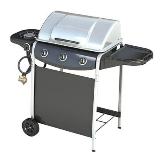
Assembly and Operating Instructions for
Photographs are not to scale.
Specifications subject to change
without prior notice.
WARNING
FOR YOUR SAFETY
If you smell gas:
1.
Shut off gas to the appliance.
2.
Extinguish any open flame.
3.
Open barbecue lid or hood.
4.
If odour continues, discontinue use and
contact your local dealer.
PDF created with pdfFactory trial version
3 Burner with Side Burner Gas BBQ
•
For outdoor use only. Not for commercial use.
•
Use only Propane regulator 37mbar.
•
Read instructions before using the appliance. Failure to follow instructions could
result in death, serious bodily injury, and/or property loss.
•
Warning: accessible parts may be very hot. Keep young children away.
•
Do not move the appliance during use.
•
Turn off the gas supply at the gas bottle after use.
•
Any modification of the appliance, misuse, or failure to follow the instructions may
be dangerous and will invalidate your warranty. This does not affect your statutory
rights.
•
Retain these instructions for future reference.
•
Leak test your barbecue annually. Check the hose connections are tight and leak
test them each time you reconnect the gas bottle.
www.pdffactory.com
Model KS10013
FOR YOUR SAFETY
1.
Do not store or use petrol or other flammable
vapours or liquids in the vicinity of this or any
other appliance.
2.
A gas bottle not connected for use shall not be
stored in the vicinity of this or any other
appliance.
0359
Advertisement

Related Manuals for Argos KS10013


Summary of Contents for Argos KS10013
- Page 1 Assembly and Operating Instructions for 3 Burner with Side Burner Gas BBQ Photographs are not to scale. Specifications subject to change without prior notice. Model KS10013 0359 • For outdoor use only. Not for commercial use. • Use only Propane regulator 37mbar.
- Page 2 A. Parts List Quantities vary according to model purchased. Specifications subject to change without prior notice. For more details on hardware, please see the corresponding Hardware Reference Diagram for your barbecue model. Code Part Grill assembly Lid handle Warming rack Cooking grill Heat tent Grease cup hanger...
- Page 3 B1. Parts Diagram Quantities vary according to model purchased. Specifications subject to change without prior notice. For more details on hardware, please see the corresponding Hardware Reference Diagram for your barbecue model. PDF created with pdfFactory trial version www.pdffactory.com...
- Page 4 B2. Hardware Reference Diagram Specifications subject to change without prior notice. M4*8 Round Head Bolt 2 PCS M4*8 Pan Head Bolt 1PC PDF created with pdfFactory trial version www.pdffactory.com...
- Page 5 C. Assembly TOOLS NEEDED FOR ASSEMBLY: Medium size flat blade or Philips/cross-point screwdriver, adjustable spanner or metric spanner set. This barbecue requires two people for assembly. Please remove all packaging materials from all individual parts before assembling. Please lay out all nuts and bolts and check lengths before assembling. Whilst every care is taken during the manufacture of this product, care must be taken during the assembly in case sharp edges are present.
- Page 6 Fig 3 Fix the Leg Cap (B10) to the Right Front Leg (B1) and Right Rear Leg (B2) as Fig 3. Hammer the Leg Cap (B10) slightly to make it fix on the legs. Fig 4 Insert the Wheels (B5) to Left Front Leg (B3) and Left Rear Leg (B4) using the Axle (E7). Then fix the Axle (E7) by R pin (E6) as Fig 4.
- Page 7 Fig 5 Connect the Upper Support (B6) with the Left Front Leg (B3) and Left Rear Leg (B4) using the M6*25 bolt (E1) and M6 nuts (E3) as Fig 5. Repeat the same connection of the Upper Support (B6) with the Right Front Leg (B1) and Right Rear Leg (B2) using the M6*25 bolt (E1) and M6 nuts (E3) as Fig 5.
- Page 8 Fig 7a Fig 7b Fig 7c Fix the burner of the Grill Assembly (A1) using M6*25 bolt (E1) and M6 nut (E3) as Fig 7a. Set the Grill Assembly (A1) on the Upper Supports (B6) and fix it by M6*40 bolt (E4) and M6 nut (E3) as Fig 7b and 7c.
- Page 9 Fig 8a Fig 8b Hang the Grease Cup Hanger (A6) and Grease Cup (A7) on the Grill Assembly (A1) as Fig 8a and 8b. Fig 9b Fig 9a Place the Heat Tent (A5) on top of each burner of the Grill Assembly (A1). Align the Heat Tent (A5) with tabs on its end against slots on the firebowl back as Fig 9a.
- Page 10 Fig 10 Put the Washer (E12) between the Lid Handle (A2) and the Lid of the Grill Assembly (A1). Align the holes and fix the Lid Handle (A2) on the Lid of the Grill Assembly (A1) using M5*10 bolts (E5) as Fig 10.
- Page 11 Fig 12a Fig 12b Install the Side Table Assembly made in Step 9 to the Right Upper Support (B6) by M6*20 Shoulder Bolt (E9) as Fig 12a and 12b. Fig 13a Fig 13b Install the Side Burner Assembly (D1) to the Left Upper Support (B6) using M6*15 bolt (E8) as Fig 13a and 13b. PDF created with pdfFactory trial version www.pdffactory.com...
- Page 12 Fig 14a Fig 14b Fix the side burner valve of the Control Panel Assembly (B7) on the side burner panel bracket of the Side Burner Assembly (D1) using M4*8 round head bolt (E10) on the top and M4*8 pan head bolt (E13) at the bottom as Fig 14a.
- Page 13 Fig 15a Fig 15b Fig 15c Fix the Side Burner Electrode (D3) on the Side Burner Assembly (D1) using M4*8 bolt (E10) as Fig 15a. Put the Side Burner (D4) through the hole of Side Burner Assembly (D1). Adjust the burner venturi against the valve as Fig 15b.
- Page 14 Fig 16 Put the Side Burner Grate (D5) on the Side Burner Assembly (D1) and align with 3 holes as Fig 16. Fig 17 Put the Cooking Grill (A4) and Warming Rack (A3) on the Grill Assembly (A1) as Fig 17. PDF created with pdfFactory trial version www.pdffactory.com...
- Page 15 Fig 18 Attach the Front Canvas (B8) to the Left Front Leg (B3) and Right Front Leg (B1) and secure the position with the velcro on the canvas edge as Fig 18. Fig 19 Connect the Side Burner Electrode (D3) to the side burner valve of the Control Panel Assembly (B7) as Fig 19.
- Page 16 Fig 20 Complete the assembly as Fig 20. PDF created with pdfFactory trial version www.pdffactory.com...
- Page 17 YOU MUST HAVE THE PROPER REGULATOR D. Important Information AND BOTTLE IN ORDER FOR THE BARBECUE TO OPERATE SAFELY AND EFFICIENTLY. USE OF Please read these instructions carefully before AN INCORRECT OR FAULTY REGULATOR IS assembly and use. DANGEROUS WILL INVALIDATE WARRANTY.
- Page 18 best cooking results. G. Operation G5. Lighting the Side Burner G1. Warning • Keep side burner free. • Before proceeding, make certain that you • Set the control knob to off and turn on the gas understand the IMPORTANT INFORMATION supply.
- Page 19 If this happens, Model Number KS10013 the gas should be immediately turned off at the Gas Category I3P (37) bottle.
- Page 20 Obstructions in gas jets or gas hose Clean jets and gas hose Windy conditions. Use BBQ in a more sheltered position Gas valve knob difficult to turn Gas valve jammed Replace gas valve Argos Limited, MK9 2W PDF created with pdfFactory trial version www.pdffactory.com...
- Page 21 3 Burner Gas BBQ with side burner Assembly Instructions - 345/0925 Please keep for future reference Dimensions Width - 125cm Depth - 55.5cm Height - 97cm Important - Please read this instructions fully before starting assembly If you need help or have damaged or missing parts, call the Customer Helpline: 08456 400800. Issue 1 - 7/9/11...
- Page 22 Safety and Care Advice Important - Please read this instructions fully before starting assembly Assembly time: approx. 45 mins. • Retain these instructions for future reference. • For outdoors use only – do not use indoors. Do not use below ground level and confined spaces. •...
- Page 23 Safety and Care Advice or tension. The hose should hang freely with no bends, folds, or kinks that could obstruct free flow of gas. Apart from the connection point, no part of the hose should touch any hot barbecue parts. Always inspect the hose for cuts, cracks, or excessive wear before use.
- Page 24 Safety and Care Advice Manual Ignition Instruction for Main Burner Insert lit match through the match-lighting hole at the side or bottom of the barbecue body. • Push in and turn the control knob anti-clockwise to the max position, the middle burner should ignite. •...
- Page 25 Safety and Care Advice Care and Maintenance Regularly clean your barbecue between uses and especially after extended periods of storage. Ensure the barbecue and its components are sufficiently cool before cleaning. Do not leave the barbecue exposed to outside weather conditions or stored in damp, moist areas. Never douse the barbecue with water when its surfaces are hot.
- Page 26 Safety and Care Advice Fixings All screws and bolts, etc. should be checked and tightened on a regular basis. Storage Store your barbecue in a cool dry place. It must be inspected on a regular basis as damp or condensation can form which may result in damage to the barbecue. It may be necessary to dry the barbecue and the inside of the cover if used.
- Page 27 If you have damaged or missing components, Components - Parts call the Customer Helpline: 08456 400800. Please check you have all the panels listed below Lid handle x1 Grill assembly x1 Cooking grill x1 Warming rack x1 Grease cup x1 Leg cap x2 Grease cup hanger x 1 Heat tent x3...
- Page 28 Components - Parts Please check you have all the panels listed below Wheel x 2 upper support x 2 Control panel assembly x 1 Side table x1 Front canvas x1 Bottom shelf x1 Side table front Side table rear Side burner assembly x1 support x1 support x1 Side burner...
- Page 29 Components - Fittings Please check you have all the panels listed below Note The quantities below are the correct amount to complete the assembly. : : : : 10mm Bolt x 8 M6 nut x 15 40mm Bolt x 8 25mm Bolt x 11 Axle x 2 10mm Bolt x 2...
- Page 30 Assembly Instructions Step 1 Put the right front leg right rear leg on the bottom shelf using 10mm bolts Fix the bolts tightly by the screwdriver. FRONT Step 2 Put the left front leg left rear leg on the bottom shelf using 10mm bolts Fix the bolts tightly by the...
- Page 31 Assembly Instructions Step 3 Fix the leg caps to the right front leg and right rear leg Hammer the leg caps slightly to make it fix on the legs. FRONT Step 4 Insert the wheels to the left front leg and the left rear leg using the axles...
- Page 32 Assembly Instructions Step 5 Connect the upper support with the left front leg and left rear leg using 25mm bolts and M6 nuts Repeat the same connection of the upper support with the right front leg right rear leg using 25mm bolts and M6 nuts Fix the bolts tightly by the...
- Page 33 Assembly Instructions Step 7 Fix the burners of the grill assembly using 25mm bolts and M6 nuts Set the grill assembly on the upper supports and fix it by 40mm bolts and M6 nuts (Do not tighten the bolts at this stage.) Align all valves on the control panel assembly...
- Page 34 Assembly Instructions Step 8 Put the grease cup hanger through the hole of the the grill assembly Hang the grease cup the grease cup hanger Step 9 Place the heat tent top of each burner of the grill assembly Align the heat tent with tabs on its end against slots on the firebowl back.
- Page 35 Assembly Instructions Step 10 Put the washers between the lid handle and the lid of the grill assembly Align the holes and fix the lid handle on the lid of the grill assembly using 10mm bolts Fix the bolts tightly by the screwdriver.
- Page 36 Assembly Instructions Step 12 Install the side table assembly made in step 11 to the upper support 15mm shoulder bolts Step 13 Install the side burner assembly to the upper support using 15mm bolts...
- Page 37 Assembly Instructions Step 14 Fix the side burner valve on the side burner panel of the side burner assembly using 8mm bolts Put the side burner knob on the side burner assembly Put the side burner and the side burner electrode through the hole of side burner assembly...
- Page 38 Assembly Instructions Step 14 Align the venturi of the side burner against the valve. Important: Make sure the valve tip goes into the venturi tube completely with good alignment. Then tighten the side burner on the side burner assembly using 8mm bolt Burner venturi Connect the electrode of the main burner and the side...
- Page 39 Assembly Instructions Step 15 Put the cooking grill the warming rack on the grill assembly Step 16 Attach the front canvas to the left front leg right front leg Secure the position with the velcro on canvas edge.
- Page 40 Assembly Instructions Step 17 Assembly is complete. If you need help or have damaged or missing parts, call the Customer Helpline: 08456 400800.
- Page 41 Technical Specification Model Number KS10013 I3P (37) Gas Category Propane Type of Gas Gas Pressure 37 mbar 359/BU/1015 Pin Number 0.84mm Injector Size (Main Burner) Injector Size (Side Burner) 0.74mm 11.0 kW Total Heat Input 8.7 kW 3 Burner Heat Input Side Burner Heat Input 2.3 kW...
- Page 42 Troubleshooting Problem Possible Cause Solution Burner will not light LP gas cylinder is empty Replace with full cylinder using the ignition Faulty regulator Have regulator checked or replace system Obstructions in burner Clean burner Obstructions in gas jets or gas hose Clean jets and gas hose Electrode wire is loose or disconnected Reconnect wire...
- Page 43 3 Burner Gas BBQ with side burner Assembly Instructions - 345/0925 Please keep for future reference Dimensions Width - 125cm Depth - 55.5cm Height - 97cm Important - Please read this instructions fully before starting assembly If you need help or have damaged or missing parts, call the Customer Helpline: 08456 400800. Issue 1 - 14/9/12...
- Page 44 Safety and Care Advice Important - Please read this instructions fully before starting assembly Assembly time: approx. 45 mins. • Retain these instructions for future reference. • For outdoors use only – do not use indoors. Do not use below ground level and confined spaces. •...
- Page 45 Safety and Care Advice or tension. The hose should hang freely with no bends, folds, or kinks that could obstruct free flow of gas. Apart from the connection point, no part of the hose should touch any hot barbecue parts. Always inspect the hose for cuts, cracks, or excessive wear before use.
- Page 46 Safety and Care Advice Manual Ignition Instruction for Main Burner Insert lit match through the match-lighting hole at the side or bottom of the barbecue body. • Push in and turn the control knob anti-clockwise to the max position, the middle burner should ignite. •...
- Page 47 Safety and Care Advice Care and Maintenance Regularly clean your barbecue between uses and especially after extended periods of storage. Ensure the barbecue and its components are sufficiently cool before cleaning. Do not leave the barbecue exposed to outside weather conditions or stored in damp, moist areas. Never douse the barbecue with water when its surfaces are hot.
- Page 48 Safety and Care Advice Fixings All screws and bolts, etc. should be checked and tightened on a regular basis. Storage Store your barbecue in a cool dry place. It must be inspected on a regular basis as damp or condensation can form which may result in damage to the barbecue. It may be necessary to dry the barbecue and the inside of the cover if used.
- Page 49 If you have damaged or missing components, Components - Parts call the Customer Helpline: 08456 400800. Please check you have all the panels listed below Lid handle x1 Grill assembly x1 Cooking grill x1 Warming rack x1 Grease cup x1 Leg cap x2 Grease cup hanger x 1 Heat tent x3...
- Page 50 Components - Parts Please check you have all the panels listed below Wheel x 2 upper support x 2 Control panel assembly x 1 Side table x1 Front canvas x1 Bottom shelf x1 Side table front Side table rear Side burner assembly x1 support x1 support x1 Side burner...
- Page 51 Components - Fittings Please check you have all the panels listed below Note The quantities below are the correct amount to complete the assembly. : : : : 10mm Bolt x 8 M6 nut x 15 40mm Bolt x 8 25mm Bolt x 11 Axle x 2 10mm Bolt x 2...
- Page 52 Assembly Instructions Step 1 Put the right front leg right rear leg on the bottom shelf using 10mm bolts Fix the bolts tightly by the screwdriver. FRONT Step 2 Put the left front leg left rear leg on the bottom shelf using 10mm bolts Fix the bolts tightly by the...
- Page 53 Assembly Instructions Step 3 Fix the leg caps to the right front leg and right rear leg Hammer the leg caps slightly to make it fix on the legs. FRONT Step 4 Insert the wheels to the left front leg and the left rear leg using the axles...
- Page 54 Assembly Instructions Step 5 Connect the upper support with the left front leg and left rear leg using 25mm bolts and M6 nuts Repeat the same connection of the upper support with the right front leg right rear leg using 25mm bolts and M6 nuts Fix the bolts tightly by the...
- Page 55 Assembly Instructions Step 7 Fix the 25mm bolts and M6 nuts on the grill assembly Set the grill assembly on the upper supports and fix it by 40mm bolts and M6 nuts (Do not tighten the bolts at this stage.) Align all valves on the control panel assembly against each venturi of the...
- Page 56 Assembly Instructions Step 8 Put the grease cup hanger through the hole of the the grill assembly Hang the grease cup the grease cup hanger Step 9 Place the heat tent top of each burner of the grill assembly Align the heat tent with tabs on its end against slots on the firebowl back.
- Page 57 Assembly Instructions Step 10 Put the washers between the lid handle and the lid of the grill assembly Align the holes and fix the lid handle on the lid of the grill assembly using 10mm bolts Fix the bolts tightly by the screwdriver.
- Page 58 Assembly Instructions Step 12 Install the side table assembly made in step 11 to the upper support 15mm shoulder bolts Step 13 Install the side burner assembly to the upper support using 15mm bolts...
- Page 59 Assembly Instructions Step 14 Fix the side burner valve on the side burner panel of the side burner assembly using 8mm bolts Put the side burner knob on the side burner assembly Put the side burner and the side burner electrode through the hole of side burner assembly...
- Page 60 Assembly Instructions Step 14 Align the venturi of the side burner against the valve. Important: Make sure the valve tip goes into the venturi tube completely with good alignment. Then tighten the side burner on the side burner assembly using 8mm bolt Burner venturi Connect the electrode of the main burner and the side...
- Page 61 Assembly Instructions Step 15 Put the cooking grill the warming rack on the grill assembly Step 16 Attach the front canvas to the left front leg right front leg Secure the position with the velcro on canvas edge.
- Page 62 Assembly Instructions Step 17 Assembly is complete. If you need help or have damaged or missing parts, call the Customer Helpline: 08456 400800.
- Page 63 8.7 kW 3 Burner Heat Input Side Burner Heat Input 2.3 kW 785 g/h Gas Consumption GB and IE Country of Destination Do not use this barbecue outside England and Ireland. This barbecue grill is imported by: Argos Limited, MK9 2NW...
- Page 64 Troubleshooting Problem Possible Cause Solution Burner will not light LP gas cylinder is empty Replace with full cylinder using the ignition Faulty regulator Have regulator checked or replace system Obstructions in burner Clean burner Obstructions in gas jets or gas hose Clean jets and gas hose Electrode wire is loose or disconnected Reconnect wire...
Need help?
Do you have a question about the KS10013 and is the answer not in the manual?
Questions and answers