
Related Manuals for IBC control F21018201


Summary of Contents for IBC control F21018201
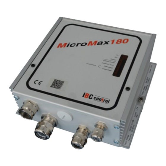
- Page 1 MANUAL CONTROL UNIT FOR ROTATING HEAT EXCHANGER MicroMax180 Article no. F21018201 control Made in Sweden...
-
Page 3: Table Of Contents
TABLE OF CONTENTS Installation instructions Mounting Safety instructions Manufacturer's declaration Description of functions Technical data Functions - DIP switch - Operational indications - Alarms - Settings via potentiometer - Push button Connection diagram Connections Checks before powering up the control unit Putting the equipment into operation EMC installation... -
Page 4: Installation Instructions
INSTALLATION INSTRUCTIONS Warning indication The control unit may only be used in perfect technical condition. Any damage that may affect safety must be dealt with immediately. Maintenance/Repairs The function of the control unit should be checked regularly. Troubleshooting and repairs may only be performed by trained personnel. -
Page 5: Safety Instructions
SAFETY INSTRUCTIONS The following symbols and references will be used in this description. These important instructions apply to personal protection and technical safety during operation. Safety instruction refers to instructions whose specific intent is to avoid the risk of personal injury and to prevent damage to equipment. -
Page 6: Manufacturer's Declaration
MANUFACTURER'S DECLARATION Manufacturer IBC control AB Brännerigatan 5 A, SE-263 37 Höganäs, Sweden Product Control unit for rotating heat exchanger Type designation MicroMax180 Article number F21018201 EU directive ap- The manufacturer's declaration of conformity with the requirements of the plied to the EMC Directive 2004/108/EC. -
Page 7: Description Of Functions
DESCRIPTION OF FUNCTIONS • The MicroMax180 is part of a range of control units adapted, with the necessary additional functions, for optimum control of rotating heat exchangers. The series consists of four sizes, MicroMax, MicroMax180, MicroMax370 and MicroMax750. All of the control units drive three-phase induction motors with associated gearing; the control unit designation denotes motor output. -
Page 8: Technical Data
TECHNICAL DATA Input voltage 1x230-240 V +/-15 % Overload 1 min/30 min 2.1 A 50/60 Hz Internal fuse **) 2.5 AT Power input, max. 390 W Acceleration time (Fixed) 30 sec Input current, max. 1.7 A Retardation time (Fixed) 30 sec Incoming fuse, max. -
Page 9: Dip Switch
DIP SWITCH Cleaning Cleaning function set to ON position. When the wheel has stopped for 30 minutes, the cleaning function is activated and the wheel rotates at minimum speed for 10 seconds. Rotation monitor Rotation monitor set to ON position. High speed* The wheel rotates at the set maximum rpm when the switch is set to ON. -
Page 10: Alarms
ALARMS All alarms remain in state. Rotation monitor Alarms and trips unless a pulse is received every 5 minutes. Probable fault cause on Magnet facing the wrong way installation - Magnetic sensor incorrectly connected (wrong polarity), see CONNECTIONS on page 10 - Too wide a gap between the magnetic sensor and magnet;... -
Page 11: Settings Via Potentiometer
Continued from previous page Phase-to-earth short circuit MicroMax180 trips immediately. Probable fault cause - Earth fault in motor or cable In the event of an earth fault, the control unit must be reset with power off. ------------------------------------------------------------------------------------------------------ Overcurrent MicroMax180 limits current to 2.4 A, above which it will trip after 4-5 seconds. -
Page 12: Connection Diagram
CONNECTION DIAGRAM U V W 13 14 15 9 10 1x 230 V 3 x230 V Thermal Alarm relay Input Rotation contact signal monitor (Max 8 A/250 V AC) 0 -10 V CONNECTIONS Switch off power before starting work on the equipment. Recommended tightening torque on terminals 0.5 Nm;... -
Page 13: Checks Before Powering Up The Control Unit
CHECKS BEFORE POWERING UP THE CONTROL UNIT Check that the control unit is connected as per instructions on page 10. Input voltage 230-240 V +/-15%, 50/60 Hz. Check that the motor is wired for 3 x 230 V. If there is an operating switch between the motor and the control unit, the motor thermal contact should be connected via the auxiliary terminal in the operating switch. -
Page 14: Emc Installation
EMC INSTALLATION Incoming EKK 3G1.5 Magnetic sensor, LiYCY 2x0.34 Not shielded Shielded Motor cable Input signal, LiYCY 2x0.34/0.5 Ölflex Classic 110 CY/7G0.5 Shielded Shielded EMC glands must be used for shielded cables. The above cables or equivalent must be used to comply with the EMC Directive. EMC GLAND NOTE! When connecting the shield to the EMC gland, it is important to do so as shown above. -
Page 15: Personal Notes
YOUR NOTES... - Page 16 IBC control AB Brännerigatan 5 A SE-263 37 Höganäs Sweden Tel. +46 (0)42-33 00 10 Fax +46 (0)42-33 03 75 www.ibccontrol.se info@ibccontrol.se...
Need help?
Do you have a question about the F21018201 and is the answer not in the manual?
Questions and answers