
Related Manuals for IBC control MicroMax1500


Summary of Contents for IBC control MicroMax1500
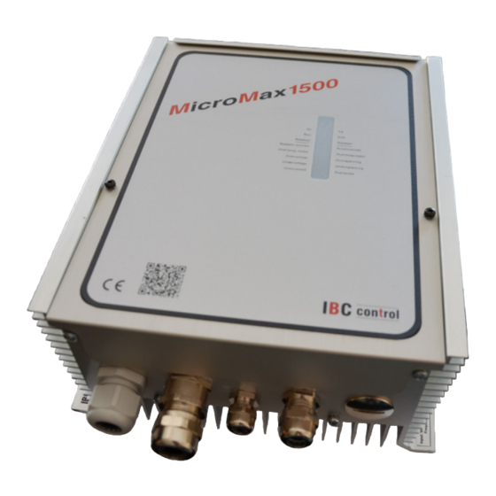
- Page 1 MANUAL Ska vara 25 mm i diameter på höjden Set of EMC-glands as an option CONTROL UNIT FOR ROTARY HEAT EXCHANGER MicroMax1500 Article no. F21150301 With adjustable boost function and threshold value control...
-
Page 3: Table Of Contents
TABLE OF CONTENTS Installation instructions Mounting Safety instructions Manufacturer's declaration Description of functions Technical data Functions - DIP switch - Operational indications - Alarms - Settings via potentiometer - Push button Connection diagram Connections 10-11 Checks before powering up the control unit Putting the equipment into operation EMC installation... -
Page 4: Installation Instructions
INSTALLATION INSTRUCTIONS Warning indication The control unit may only be used in perfect technical condition.Any damage that may affect safety must be dealt with immediately. Maintenance/Repairs The function of the control unit should be checked regularly. Troubleshooting and repairs may only be performed by trained personnel. -
Page 5: Safety Instructions
SAFETY INSTRUCTIONS The following symbols and references will be used in this description. These important instructions apply to personal protection and technical safety during operation. “Safety instructions” refers to instructions whose specific intent is to avoid the risk of personal injury and to prevent damage to equipment. -
Page 6: Manufacturer's Declaration
Manufacturer IBC control AB Brännerigatan 5 A, SE-263 37 Höganäs, Sweden Product Control unit for rotary heat exchanger Type designation MicroMax1500 EU directive The manufacturer's declaration of conformity with the applied to the requirements of the EMC Directive 2014/30/EU. product... -
Page 7: Description Of Functions
DESCRIPTION OF FUNCTIONS The MicroMax1500 is part of a range of control units adapted, with the necessary • additional functions, for optimum control of rotary heat exchangers. The series consists of five sizes, MicroMax, MicroMax180, MicroMax370, MicroMax750 and MicroMax1500. All of the control units drive three-phase induction motors with associated gearing, the control unit designation denotes motor output. -
Page 8: Technical Data
TECHNICAL DATA Connection voltage 1x230-240 V +/-10 % Ambient temperature, -25 - +45 50 Hz non condensing Power input, max. 1900 W Protection form IP54 Input current, max. 9,5 A Weight 2.9 kg External fuse, max. 16 A Dimensions, HxWxD 233x205x104 mm Exact value cannot be obtained with a digital measuring Output voltage*) -
Page 9: Dip Switch
DIP SWITCH Cleaning function Cleaning function set to ON position. When the wheel has stopped for 30 minutes, the cleaning function is activated and the wheel rotates at minimum rpm for 10 seconds. Rotation monitor Rotation monitor set to ON position. High speed*) The wheel rotates at the set maximum rpm when the switch is set to ON. -
Page 10: Alarms
Alarms and trips in the event of a phase-to-phase or phase-to-earth short circuit and overcurrent. Short circuit phase-phase orphase-earth (earth fault) MicroMax1500 trips immediately. Probable fault cause - Motor winding fault Measure motor resistance, it should be identical on all phases. -
Page 11: Settings Via Potentiometer
Continued from previous page Overcurrent MicroMax1500 limits current at 10 A and trips then after 4-5 s. Probable fault cause - The motor is too small in relation to wheel diameter - Wheel rotation sluggish - Damaged motor, e.g. bearing fault Measure current. -
Page 12: Connection Diagram
CONNECTION DIAGRAM U V W 13 14 15 9 10 A1 A2 1x 230 V 3 x 230 V Thermal Alarm relay 0-10 V Rotation Manual speed Max 1500 W contact monitor (Max 2 A / 250 V AC) CONNECTIONS Switch off power before starting work on the equipment. -
Page 13: Checks Before Powering Up The Control Unit
Continued from previous page Input signal 0-10 V. (2-3) Plus connected to terminal 2, minus to terminal 3. Rotation monitor White cable connected to terminal 9, brown to terminal 10. (9-10) The magnet is installed with south side (S) towards the sensor. Max. -
Page 14: Putting The Equipment Into Operation
PUTTING THE EQUIPMENT INTO OPERATION Should be done in sequence. Check that the motor rotates in the right direction in relation to the wheel's direction of rotation. In the event of a fault, switch two phases to the motor. Adjustment of Set the “High Speed”... -
Page 15: Emc Installation
EMC INSTALLATION Rotation monitor, LiYCY 2x0.34 Connection voltage 3G2,5 Shielded Not shielded Motor cable Input signal, LiYCY 2x0.34/0.5 Ölflex Classic 110 CY,/7G1,5 Shielded Shielded EMC glands must be used for shielded cables. The above cables or equivalent must be used to comply with the EMC Directive. EMC GLAND NOTE! When connecting the shield to the EMC gland, it is important to do so as shown above. - Page 16 IBC control AB Brännerigatan 5 A SE-263 37 Höganäs Sweden Tel. +46 42 33 00 10 www.ibccontrol.se info@ibccontrol.se...
Need help?
Do you have a question about the MicroMax1500 and is the answer not in the manual?
Questions and answers