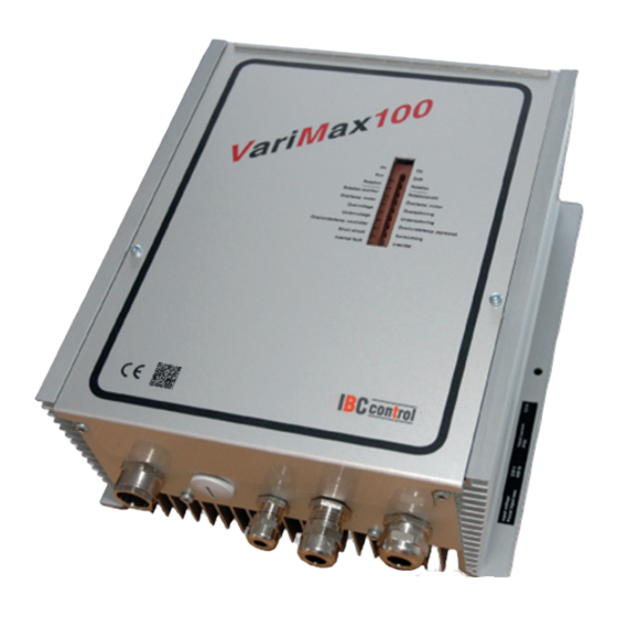
Summary of Contents for IBC control VariMax100
- Page 1 MANUAL CONTROL UNIT FOR ROTATING HEAT EXCHANGER VariMax100 Art. no. F21100201 control Made in Sweden...
-
Page 3: Table Of Contents
PAGE REFERENCE Installation instructions Mounting Safety instructions Manufacturer's declaration Description of functions Technical data Functions DIP switches - Operational indications - Alarms - Adjustments via potentiometer - Push buttons Connection diagram Connections Input signal/Rotation speed Checks before switching on the control unit Putting the equipment into operation EMC installation... -
Page 4: Installation Instructions
INSTALLATION INSTRUCTIONS Warning indication The control unit must only be used in perfect technical condition. Any damage that may affect safety must be dealt with immediately. Maintenance/Repairs The function of the control unit should be checked regularly. Troubleshooting and repairs must only be performed by trained personnel. -
Page 5: Safety Instructions
SAFETY INSTRUCTIONS The following symbols and references will be used in this description. These important instructions apply to personal protection and technical safety during operation. "Safety instruction" represents instructions that are intended to avoid the risk of personal injury and to prevent damage to equipment. -
Page 6: Manufacturer's Declaration
MANUFACTURER'S DECLARATION Manufacturer IBC control AB Brännerigatan 5 A, SE-263 37 Höganäs, Sweden Product Control unit for rotating heat exchanger Type designation VariMax100 Article number F21100201 EU directive The manufacturer's declaration of conformity with the requirements of the applied to the EMC Directive 2004/108/EC. -
Page 7: Description Of Functions
3-phase stepper motor. All control units have an input signal of 0-10 V. • VariMax100 is designed for wheels up to 3900 mm with a wheel speed of max. 12 rpm. If the wheel requires a faster wheel speed, the rotor diameter should be reduced. -
Page 8: Technical Data
TECHNICAL DATA CONTROL UNIT Connection voltage 1x230-240 V +/-15% Output frequency 0-333 Hz 50/60 Hz Acceleration and 30 sec Power input, max. 500 W retardation time Ambient temperature, Input current, max. 2,2 A -30 - +45 non condensing External fuse, max. 10 A Protection form Type 1/IP54... -
Page 9: Dip Switches
DIP SWITCHES Cleaning Cleaning function connected in ON position. When the wheel has been still for 30 minutes, the cleaning function is activated and the wheel rotates for 20 seconds at 12 rpm. Rotation monitor Rotation monitor connected in ON position. High speed *) The wheel rotates at the set max. -
Page 10: Adjustments Via Potentiometer
Continued from previous page Probable fault cause on - Magnet turned the wrong way installation - Magnet transmitter incorrectly connected (wrong polarity), see CONNECTIONS on page 9 - Too big a gap between magnet transmitter and magnet, max. 15 mm Probable fault cause in - Broken belt operation... -
Page 11: Connection Diagram
CONNECTION DIAGRAM (Max 2 A / 250 V AC) 11 12 14 15 A1 A2 9 10 1 x 230 V Alarm relay Man. Input Rotation Reset Thermal Stepper motor 3-phase speed signal monitor contact 0 - 10 V CONNECTIONS The voltage must be switched off before undertaking any work on the equipment. -
Page 12: Input Signal/Rotation Speed
INPUT SIGNALS/ROTATION SPEED Rotation speed [%] Input signal - rotation speed The input signal is directly proportional to the efficiency of the wheel, which means that input signal and rotation speed are as per adjoining diagram. Input signal 0-10 V CHECKS BEFORE SWITCHING ON THE CONTROL UNIT Check that the control unit is connected as per instructions on page 9. -
Page 13: Emc Installation
EMC INSTALLATION Motor cable Incoming EKK 3G1.5 Not shielded Ölflex Classic 110 CY/7G0.75 Shielded Magnet transmitter, LiYCY 2x0.34 Input signal, LiYCY 2x0.34/0.5 Shielded Shielded EMC glands must be used for shielded cables. The above cables, or equivalent, must be used to comply with the terms of the EMC Directive. EMC GLAND NOTE! When connecting the shielding to the EMC gland, it is important to connect as shown above. -
Page 14: Personal Notes
PERSONAL NOTES... - Page 15 PERSONAL NOTES...
- Page 16 IBC control AB Brännerigatan 5 A SE-263 37 Höganäs Sweden Tel. +46 (0)42-33 00 10 Fax +46 (0)42-33 03 75 www.ibccontrol.se info@ibccontrol.se...


Need help?
Do you have a question about the VariMax100 and is the answer not in the manual?
Questions and answers