
Related Manuals for IBC control F21025305


Summary of Contents for IBC control F21025305
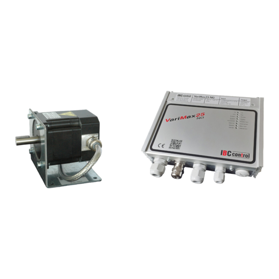
- Page 1 MANUAL Ska vara 25 mm i diameter på höjden CONTROL UNIT FOR ROTARY HEAT EXCHANGER VariMax25 Article no. F21025305 control...
-
Page 3: Table Of Contents
TABLE OF CONTENTS Installation Instructions Safety instructions Manufacturer’s declaration Declaration of conformity Description of functions Mounting Technical data, control unit Technical data, motor Functions - DIP switch - Operational indications - Alarms - Settings via potentiometer - Reset Connection diagram Connections 10-11 Input signal/Rotation speed... -
Page 4: Installation Instructions
INSTALLATION INSTRUCTIONS Warning indication The control unit must be in perfect technical condition before use. Damage that can affect safety must be remedied immediately . Maintenance/Repairs Control unit function should be checked regularly. Troubleshooting and repairs may only be done by trained personnel. -
Page 5: Manufacturer's Declaration Declaration Of Conformity
MANUFACTURER'S DECLARATION DECLARATION OF CONFORMITY Manufacturer IBC control AB Brännerigatan 5 A SE-263 37 Höganäs Sweden Tel: +46 42 33 00 10 Product Control unit for rotary heat exchanger Type designation VariMax25 NG Applicable EMC Directive 2014/30/EU EU Directives Low Voltage Directive 2014/35/EU... -
Page 6: Description Of Functions
DESCRIPTION OF FUNCTIONS • The VariMax25 NG is part of a new range of control units that, with the necessary additional functions, are suitable for the optimum control of rotary heat exchangers. The series comes in two sizes, the VariMax25 NG and VariMax50 NG. Both the control units operate 3-phase stepper motors. -
Page 7: Mounting
Continued from previous page • As an alternative, the VariMax25 NG can have an external rotation monitor (magnet mounted on the rotor with an associated rotation monitor). This is connected at terminal connections 9 and 10, and the DIP switch for the “External rotation monitor” should be in the ON position. -
Page 8: Technical Data, Control Unit
TECHNICAL DATA, CONTROL UNIT Connection voltage 1×230-240 V +/-15% Output frequency 0-291 Hz 50/60 Hz Acceleration and 30 sec Power input max 97 W retardation time Ambient temperature, Input current max 0.8 A -40 - +45 non condensing External fuse, max 10 A Protection form IP44... -
Page 9: Dip Switch
DIP SWITCH Cleaning function Cleaning function connected in ON position. When the rotor has stopped for 10 minutes, the cleaning function is activated and the rotor starts to rotate. As advance warning, the rotor rotates with a motor speed of 5 rpm for the first 6 seconds, following which the rotor stops for 3 seconds. -
Page 10: Alarms
ALARMS In the case of an alarm, the control unit will restart after 30 seconds. The relevant red LED will light up for the same period of time (30 seconds). After restart, the LED is extinguished; this takes place twice. The third time, the alarm relay closes and the alarm "moves on". -
Page 11: Settings Via Potentiometer
Motor fault Motor temperature The control unit regulates power and makes sure the motor will not overheat. Short circuit Alarms and trips in the event of short circuit phase-phase or phase-earth. Probable cause of fault - Short circuit between phases in cable or motor - Short circuit between phase-earth in cable or motor - Interruption to one phase in cable or motor - No motor or wrong motor connected... -
Page 12: Connection Diagram
CONNECTION DIAGRAM 15 s. (Max 0,5 A 30 V AC/DC) U V W A1 A2 9 10 11 12 14 15 D1 Com Reset Alarm relay Modbus 1 x 230 V Stepper motor Manual Input External 3-phase speed signal rotation 0 - 10 V monitor CONNECTIONS... -
Page 13: Input Signal/Rotation Speed
Continued from previous page 12 V output Output for 12 V DC. Terminal connection 3 is minus (-), (3-11) terminal connection 11 is plus (+). Max 50 mA. External rotation If an external rotation monitor is used, this is connected as shown below. monitor White cable connected to terminal 9, brown to terminal 10. -
Page 14: Checks Before Powering Up The Control Unit
CHECKS BEFORE POWERING UP THE CONTROL UNIT Check that the control unit is connected as per instructions on page 10. Connection voltage 1x230-240 V +/-15%, 50/60 Hz. Check that the input signal is 0-10 V. Check that rotation monitor and cleaning function are connected. PUTTING THE EQUIPMENT INTO OPERATION Should be done in sequence Check that... -
Page 15: Emc Installation
EMC-INSTALLATION Connection voltage External rotation monitor 3G1.5 LiYY 2×0.34 Not shielded Not shielded Motor Input signal NCY-HAR/UL/CSA 4G0,75 2×0.34/0.5 Shielded Does not need shielded EMC glands must be used for shielded cables. The above cables or equivalent must be used to comply with the EMC Directive. EMC GLAND NOTE! When connecting the shielding to the EMC gland, it is important to connect as shown above. - Page 16 IBC control AB Brännerigatan 5 A SE-263 37 Höganäs Sweden Tel. +46 42 33 00 10 www.ibccontrol.se info@ibccontrol.se...
Need help?
Do you have a question about the F21025305 and is the answer not in the manual?
Questions and answers