Table of Contents
Advertisement
Advertisement
Table of Contents

Subscribe to Our Youtube Channel
Related Manuals for Autool CT500


Summary of Contents for Autool CT500
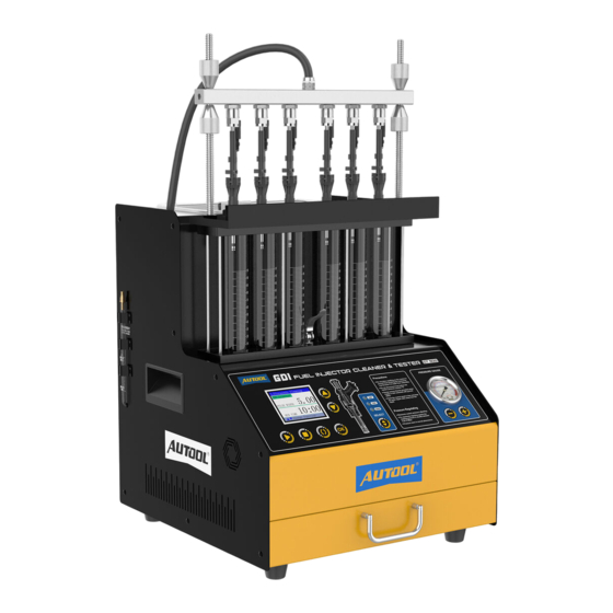
- Page 1 AUTOOL CT500 GDI Fuel Injector Cleaner & Tester User Manual 用户手册...
-
Page 2: Table Of Contents
TABLE OF CONTENTS Cautions ......................2 Warning ......................2 Product Introduction ..................3 Overview ......................3 Main functions ....................3 Main features ....................3 Working environment ..................4 Technical parameters ..................4 Product Structure ....................5 Structure diagram.................... 5 Operation panel diagram................. 6 Operation Process ..................... -
Page 3: Cautions
CAUTIONS Warning Before using the instrument, please read this manual careful- ly for proper operation. Since the test device is part of quartz glass, it is easy to break, so do not place other objects around the equipment to avoid bumping and breaking. -
Page 4: Product Introduction
PRODUCT INTRODUCTION Overview Fuel injector diagnostic and cleaning equipment is a mechatronics product that combines ultrasonic cleaning technology and micro- computer oil pressure closedloop control cleaning and detection technology. This product simulates various operating conditions of the engine, and cleans and inspects the fuel injectors of various automobiles and motorcycles. -
Page 5: Working Environment
● Design with HD color display, makes the operation clear and easy to learn. The oil tank liquid level is displayed visually, and the detection ● liquid can be recycled. ● Bright background light, you can clearly see the various situations of the fuel injector when it is working. -
Page 6: Product Structure
PRODUCT STRUCTURE Structure diagram Lock pole Lock nut Top oil inlet connector Oil rail Glass measuring cylinder Oil drain handle Operation panel Pressure gauge Portable drawer Oil outlet pipe Ultrasonic cleaning tank Signal wire Power switch Power socket... -
Page 7: Operation Panel Diagram
Cleaning agent Testing agent liquid level drain valve Operation panel diagram TFT color screen Function buttons Voltage selection Pressure adjustment of injectors... -
Page 8: Operation Process
OPERATION PROCESS Ultrasonic Ultrasonic cleaning is to use the penetrating and cavitation shock cleaning waves generated when ultrasonic waves propagate in the medium, and powerfully clean objects with complex shapes, cavities and pores to completely remove stubborn carbon deposits on the fuel injector. -
Page 9: Injector Diagnostic
NOTE During the cleaning process, you can hear the intermittent (approximately 5 seconds) vibrating sound when you take the fuel injector out and put it to your ear, so you can judge whether the fuel injector is working normally. Ultrasonic cleaning is strictly prohibited when there is no cleaning agent in the ultrasonic tank to avoid equipment damage. - Page 10 ① ⑦ ② ③ ⑧ ④ ⑤ ⑥ Top-in fuel injector installation diagram Oil outlet pipe Oil rail Top oil inlet connector Injectors Upper plate seat Glass measuring cylinder Lock nut Lock pole ● Select the top oil inlet connector from the accessories and install it into the oil separator.
- Page 11 ● Turn the pressure adjustment knob to adjust the pressure to 0.25 ~ 0.3MPa. (In the electronic injection system, the general oil pressure works at 0.25 ~ 0.3MPa) ● The working time gradually decreases. When it is 0, the system automatically stops.
- Page 12 10s, and the user does not need to set it separately. The system will automatically and continuously cycle three times to simulate the working condition and fuel injection volume of the fuel injector when the engine is idling, medium speed, and high speed. 07 Leakage Test Select “07 Leakage Test”.
- Page 13 NOTE Flow Balance Test The flow balance test shall be carried out at different speeds. When the liquid level in the measuring cylinder is 2/3 of the measuring cylinder, pause or stop work to observe the balance of the fuel injection volume. The deviation of the fuel injection volume of all fuel injection nozzles on a vehicle should not exceed 2%.
-
Page 14: Storage And Maintenance
14 Wide Pulse Injection Test ● Press the up or down key to select “Item 14 Wide Pulse Injec- tion Test”. Other steps are the same as in item 13. ● 15 Continuous Injection Test ● Press the up or down key to select “Item 15 Continuous Injec- tion Test”. -
Page 15: Maintenance Service
MAINTENANCE SERVICE Our products are made of long-lasting and durable materials, and we insist on perfect production process. Each product leaves the factory after 35 procedures and 12 times of testing and inspec- tion work, which ensures that each product has excellent quality and performance. -
Page 16: Warranty
Disclaimer All information, illustrations, and specifications contained in this manual, AUTOOL resumes the right of modify this manual and the machine itself with no prior notice. The physical appearance and color may differ from what is shown in the manual, please refer to the actual product. -
Page 17: Return & Exchange Service
RETURN & EXCHANGE SERVICE ● If you are an AUTOOL user and are not satisfied with the Return & AUTOOL products purchased from the online authorized Exchange shopping platform and offline authorized dealers, you can return the products within seven days from the date of receipt;...
Need help?
Do you have a question about the CT500 and is the answer not in the manual?
Questions and answers