Mitsubishi Electric JT-MC106G-W-NA Handbook
Hide thumbs
Also See for JT-MC106G-W-NA:
- Instruction manual (12 pages) ,
- Installation manual (32 pages)

Related Manuals for Mitsubishi Electric JT-MC106G-W-NA


Summary of Contents for Mitsubishi Electric JT-MC106G-W-NA
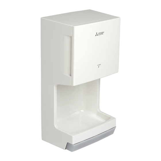
- Page 1 June 2023 No. U201-A HAND DRYER HANDBOOK MODELS JT-MC106G-W-NA Nameplate Warning: Repair work must be performed by the manufacturer, its service agent or a similarly qualified person in order to avoid hazards.
-
Page 2: Table Of Contents
Contents 1. Safety precautions ..............3-4 2. Features ..................4 3. Names and functions of components ........4-5 4. Specifications ................6 5. Outside dimensions ..............6 6. Electrical wiring diagram ............. 7 7. Circuit board diagram ..............8 8. Principles of operation ............9-10 9. -
Page 3: Safety Precautions
1. Safety precautions Read the following precautions thoroughly before the maintenance, and then inspect and repair the product in a safe manner. The types and levels of danger that may arise if the product is handled incorrectly are described with the warning symbols shown below. -
Page 4: Features
Request for repair ● Before repairs, take the product off the wall. ● Inspect the grounding condition, and repair it if it is incomplete. Make sure that a circuit breaker or an overload protection device is installed, if it is not installed, recommend the dealer to install one. ●... - Page 5 (2) How to open/close the front cover How to open the front cover 1. Pull the tab to unlock the front cover. 2. Hold the handle on the right hand 3. Open the front cover. side of the main unit. Main unit Main unit Handle...
-
Page 6: Specifications
(Vac) (Hz) 355 mph 11.5 lb 1.3 pt JT-MC106G-W-NA (0.6 ℓ ) Single phase (150 m/s) (5.2 kg) • Air speed is calculated from the static pressure measured by the pitot tube (at the nozzle). • Noise is the A range value measured in an anechoic room. (Average of the three points: 2 m from the front and both sides of the unit.) -
Page 7: Electrical Wiring Diagram
6. Electrical wiring diagram ─ 7 ─... -
Page 8: Circuit Board Diagram
7. Circuit board diagram Circuit board diagrams and check points Display circuit board (JT-33D) Sensor circuit board (JT-33S) Reset input (IC1 11P) Clock frequency 8 MHz 12.6 V (IC1 15P) (C125) Power circuit board (JT-33P) Control circuit board (JT-33M) Power supply voltage (CN2 4P) (CN2 7P) 120 V AC... -
Page 9: Principles Of Operation
8. Principles of operation Descriptions of circuit operation ( 1 ) Notes for turning the power ON / OFF 1 When the power is turned ON, the power light (LED 1) turns on after 1.5 seconds, and the hand dryer be- comes ready for operation. - Page 10 (5) Operating procedures for the test mode: indicating the number of operation/ operating time 1 How to start the test mode: Turn ON the power while holding down both of the heater switch and sensor switch. At this time, the power light blinks fast (ON for 0.1 seconds/OFF for 0.1 seconds).
-
Page 11: Troubleshooting
9. Troubleshooting Work precautions • When servicing, recreate the malfunction two or three times before starting repairs. • When servicing, always take care to keep proper footing. • Before starting the service, always unplug the power cord from the outlet, or turn off the circuit breaker when no power cord plug is provided. - Page 12 Error Display Cause Check Method and Remedy Tilted or fallen Make sure that the LEDs on the display circuit board are upright. Sensor Check Malfunction of Check if the connector CN8 on the display circuit board or CN7 on the display circuit the control circuit board is disconnected.
- Page 13 Error Display Cause Check Method and Remedy Connector dis- Check if the lead wire connectors between the motor and the Sensor Check connection for the power circuit board are disconnected. motor Motor brush at the Replace the blower (assembly). end of its life (Motor error) Motor lock Check if the motor vanes are locked.
- Page 14 Troubles without error display Symptom Cause Check Method and Remedy The hand dryer does not Malfunction of the After checking that the connector is securely connected, meas- blow warm air. heater switch ure the resistance across the heater switch on the display circuit board.
-
Page 15: How To Call
10. How to call Symptom Remedy 1 The hand dryer does The power light is not 1 If the power wires are disconnected, securely connect not blow air even turned on. them to the terminal block. though hands are 2 If the power is OFF, turn it ON. inserted. -
Page 16: Overhauling Procedures
12. Overhauling procedures Work precautions • Before replacing parts, follow the instructions described in the troubleshooting. • When servicing, always take care to keep proper footing. • Before starting the service, always unplug the power cord from the outlet, or turn off the circuit breaker when no power cord plug is provided. - Page 17 Assembly precautions • Run the lead wires through the groove of the blower cover. (Indicated by ) • Take care not to pinch the lead wires. • After installing the circuit board, make sure that the LEDs are upright. Assembly precaution Run the lead wires through the claw of the blower case.
- Page 18 (4) Power circuit board (JT-33P) 1 Remove the panel (assembly).→ See (2) 1 to 3. 2 Unscrew the clamping screw for the terminal block (TB) cover. (One PT screw 4 x 8, indicated by ) TB cover 3 Unscrew the terminal block clamping screw. Terminal block Connector (One PP screw 4 x 25, indicated by )
- Page 19 8 Unscrew the PCB case clamping screws. (Two PTT screws 4 x 14, indicated by ) PCB case 9 Unscrew the heat sink clamping screws. (Two SW PW PP scr M4, indicated by ) 0 Unscrew the clamping screw for the power circuit board. Heat sink (One PTT screw 4 x 14, indicated by ) a Remove the power circuit board (JT-33P).
- Page 20 Assembly precautions • Run the heater lead wires as shown in the picture at right. • Fit the thermal fuse parts into the groove of the heater fittings. (Indicated by ) (6) Blower (assembly) (Thermal fuse of the motor) 1 Disconnect the blower lead wires from the power circuit board (JT- 33P).
- Page 21 4 Unscrew the blower cover clamping screws. Blower cover (Four PTT screws 4 x 14, indicated by ) Assembly precaution Tighten the screws in a crisscross pattern. 5 Remove the cord bush. Cord bush 6 Remove the blower stopper. Blower (assembly) 7 Remove the blower (assembly).
-
Page 22: Parts Catalog
13. Parts catalog Please note the following when using the parts catalog. 1. When ordering parts, the part number, part name, and the number of parts are required. 2. It may take time for you to receive the parts. Make an inquiry about a rush order. 3. - Page 23 JT-MC106G-W-NA Body parts 6 pcs. 1 pc. 1 pc. shows accessory parts. ─ 23 ─ JT-MC106G-W-NA...
- Page 24 Body parts JT-MC106G-W-NA Critical Q'ty Name of part Parts No. Remarks pcs/unit safety Decorated panel Y45 634 802 Wiring diagram Y45 634 362 Spl screw 4x14 Y45 650 049 Panel support Y45 650 886 Filter Y45 650 853 Panel (assy)
- Page 25 Blower parts ─ 25 ─ JT-MC106G-W-NA...
- Page 26 Blower parts JT-MC106G-W-NA Critical Q'ty Name of part Parts No. Remarks pcs/unit safety LED fix piece Y45 650 887 Circuit board Y45 627 172 JT-33D Lead wire Y45 650 281 Micon-Display Circuit board Y45 634 172 JT-33M3 ...
- Page 27 Circuit board parts ─ 27 ─ JT-MC106G-W-NA...
- Page 28 Circuit board parts JT-MC106G-W-NA Critical Q'ty Name of part Parts No. Remarks pcs/unit safety PT screw 4x8 Y45 650 008 PCB cover Y45 650 851 Circuit board Y45 634 171 JT-33P3 PCB fix plate Y45 627 807 Cord bush...
Need help?
Do you have a question about the JT-MC106G-W-NA and is the answer not in the manual?
Questions and answers