Table of Contents
Advertisement
Quick Links
MODEL
JT-MC206GS-W-E
Unit color
-W
(White)
INSTALLATION MANUAL
Read the manual thoroughly before beginning installation to ensure the unit is installed safely and correctly.
Local installation standards should be obeyed and installation should be performed by the dealer or a qualifi ed
professional.
The "INSTRUCTION MANUAL" is for the customer. Be sure to hand it to the customer.
INDEX
■ How to open/close the front cover
Hand dryer
Location of Model Name display
Location of power supply voltage display
For Dealers and Installers
2
3
3
3
4
5
5
5
5
6 - 9
10
11
11
11
12
12
− 1 −
1209875HF0501
Single-phase 220 - 240V AC
GB
Advertisement
Table of Contents

Related Manuals for Mitsubishi Electric Jet Towel JT-MC206GS-W-E


Summary of Contents for Mitsubishi Electric Jet Towel JT-MC206GS-W-E
-
Page 1: Table Of Contents
1209875HF0501 Hand dryer MODEL JT-MC206GS-W-E Location of Model Name display Unit color (White) Location of power supply voltage display Single-phase 220 – 240V AC For Dealers and Installers INSTALLATION MANUAL Read the manual thoroughly before beginning installation to ensure the unit is installed safely and correctly. Local installation standards should be obeyed and installation should be performed by the dealer or a qualifi... -
Page 2: Safety Precautions
Safety Precautions The dangers arising from improper handling and the extents of the dangers are classified and explained as shown below. The following may lead to death or serious Warning personal injury if handled incorrectly. Do not install in locations where they may be leakages of combustible gas. -
Page 3: Pre-Installation Checks
Pre-installation checks Warning Single-phase 220 – 240V AC power is used. Using the incorrect power supply may cause fi res, electric shocks or malfunctions. ■ Checking the installation environment Do not install the unit in the following types of locations. ... -
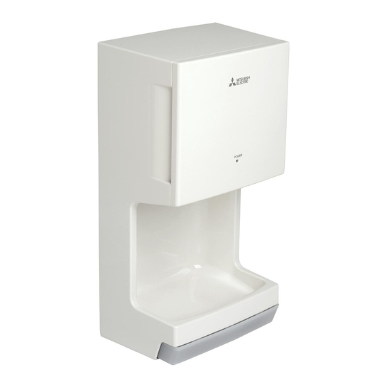
Page 4: Names Of Parts And External Dimensions
Names of parts and external dimensions ■ Main unit Power cord hole (rear) Installation panel Air fi lter Power light 16.5 Drain tank Unit (mm) NOTE Confi rm the details in the "Installation conditions" (Page 5). ■ Front Inside the front cover Power light Front Power switch... -
Page 5: Installation Conditions
Installation conditions ■ Required space for installation Rear side Top side Unit (mm) Be sure to secure at least the Caution distances listed in the right- Isolation Location hand table from walls, fl ammable distance Main (combustible) materials and so unit Above Left side... -
Page 6: Installation Method
Installation method For confi rmation □ Single-phase 220 – 240V AC power is being used (using the incorrect power supply may cause fi res, electric shocks or malfunctions). □ The ground fault circuit interrupter is attached (not attaching a ground fault circuit interrupter may result in electric shocks). - Page 7 Installation method - continuation 1. Remove the drain tank. Drain tank 2. Open the front cover and remove the Air fi lter Air fi lter air fi lter. ※ Refer to "How to open/close the front cover" (Page 11). Main unit Open panel Pull the tab and open the front...
- Page 8 Installation method - continuation 1. Push the power cable for exclusive Power cord hole Power cable wiring through the power cord hole at the rear of the base. Power cable Power cord hole 2. Engage the base with the 2 hooks on the installation panel.
- Page 9 Installation method - continuation 1. Place the power cable through the Terminal block cover mounting cord bushing and reattach it to the screw circuit case with the terminal block Terminal cover mounting screw. block cover Base 2. Check that the power cable and wires are not pinched anywhere.
-
Page 10: Test Run
Test Run Step What to check for Check Is the proper power being used? Check the power supply (JT-MC206GS-W type: Single-phase 220 – 240V AC voltage Incorrect power supply may cause malfunctions or low wind power. Turn the ground fault circuit interrupter on. -
Page 11: Initial Setting Checks
Initial setting checks ■ How to open/close the front cover How to open the front cover Pull the tab for opening the Hold the handle are on the Open. front cover. right hand side of the main unit. Main unit Main unit Handle... -
Page 12: Turning The Heater On
Initial setting checks - Continuation ■ Turning the heater on Open the front cover. Open Press the air speed switch or the heater switch Front cover and let the settings light turn on. Turn the heater switch "ON". ※ The heater may not operate during continued use as there is the danger of scalding when the temperature of the warm air Heater switch rises. - Page 13 2006/66/EC Article 20 Information for end-users and Annex II. Français English Votre produit Mitsubishi Electric est conçu et fabriqué avec des matériels et des composants de qualité supérieure qui peuvent être Your MITSUBISHI ELECTRIC product is designed and recyclés et/ou réutilisés.
- Page 14 Var snäll och hjälp oss att bevara miljön vi lever i! Nederlands Dansk Mitsubishi Electric producten zijn ontwikkeld en gefabriceerd uit Dit produkt fra MITSUBISHI ELECTRIC er designet og fremstillet eerste kwaliteit materialen. De onderdelen kunnen worden med kvalitetsmaterialer og komponenter, der kan genindvindes gerecycled en/of worden hergebruikt.
- Page 15 Mitsubishi Electric Corporation Head Office: Tokyo Bldg., 2-7-3, Marunouchi, Chiyoda-ku, Tokyo 100-8310, Japan Manufacturer Authorised representative in EU: Mitsubishi Electric Europe B.V.: 1 George Street, Harman House, Uxbridge, Middlesex, UB81QQ Commercial registration no. 33279602 Motor Power Input (kW) 0.02 Flow Rate (m...
Need help?
Do you have a question about the Jet Towel JT-MC206GS-W-E and is the answer not in the manual?
Questions and answers